Measurement Computing Daq PC-Card User Manual
Page 34
DaqBook/100, /112, /120, /200, /216
Daq* Hardware
3-4
10-18-00
DaqBook/DaqBoard/Daq PC-Card User’s Manual
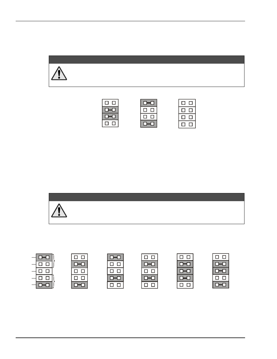
External Analog Expansion Power (JP1)
This 4×2 header (JP1) has 3 possible settings. If analog option cards (DBKs) are used, the JP1 pins are set
to provide +15 and -15 VDC to the cards. If such cards are not used, the counter/timer CTR0 is available,
and JP1 must be set accordingly. The default setting is for use of analog option cards.
&$87,21
If using a DBK32A Auxiliary Power Supply or a DBK33 Triple-Output Power Supply
Card, the JP1 shunt jumpers must be entirely removed. Placing the jumpers on
-OCTOUT and -OCLKIN will damage the 8254 timer chip. Refer also to the
Power
Management
section in the chapter
DBK Option Cards and Modules
.
DAC Reference Selection (JP2)
This 5×2 header (JP2) allows you to select internal or external voltage references for the two separate
analog outputs. If the internal -5 VDC reference is selected, either DAC can output from 0 to +5 VDC as
the register count varies from 0 to 4095 (12-bit). If an external voltage reference is desired (up to +10 VDC
or –10 VDC), the shunt jumpers must be set accordingly. There is also a provision to allow the outputting
of a simultaneous Sample-Hold command signal on the DAC1-REFIN pin with the DAC1 set up for an
internal reference.
&$87,21
The SSH setting cannot be used at the same time as a DAC1 external reference due to a
potentially damaging conflict on P1 pin #26. The defaults are both DAC0 and DAC1 set
to Internal Reference.
Note: The SSH setting is used with DBKs: 2, 4, 5, 7, 17, 50, and 51. Refer to the DBK chapter (4) as
needed.
JP 2
JP 2
JP 2
JP 2
JP 2
Fa cto ry D e fa u lt
D A C 0 E xte rn al R e f
D A C 1 E xte rn al R e f
D A C 0 E xte rn al R e f
D A C 1 In te rn al R e f
D A C 0 In te rn al R e f
D A C 1 E xte rn al R e f
D A C 0 In te rn al R e f
D A C 1 In te rn al R e f
D A C 0 E xte rn al R e f
D A C 1 In te rn al R e f
w ith S S H
D A C 0 In te rn al R e f
D A C 1 In te rn al R e f
w ith S S H
E X T
IN T
S S H
IN T
E X T
D A C 1
D A C0
JP 2
JP2 DAC Reference Settings
JP 1
-1 5 V
-O C TO U T
-O C L K IN
+1 5 V
A n a lo g O ptio n
C ard U se
JP 1
-1 5V
-O C TO U T
-O C L K IN
+1 5 V
C o un te r/Tim e r U se
(1 6-bit M o d e O nly)
JP 1
-1 5 V
-O C TO U T
-O C L K IN
+1 5 V
D B K 3 2A o r D B K 3 3
O p tio n C a rd U se
JP1 External Analog Expansion Settings