Measurement Computing DaqBook 2000 Series Installation User Manual
Page 37
Appendix E
968596
System Expansion E-5
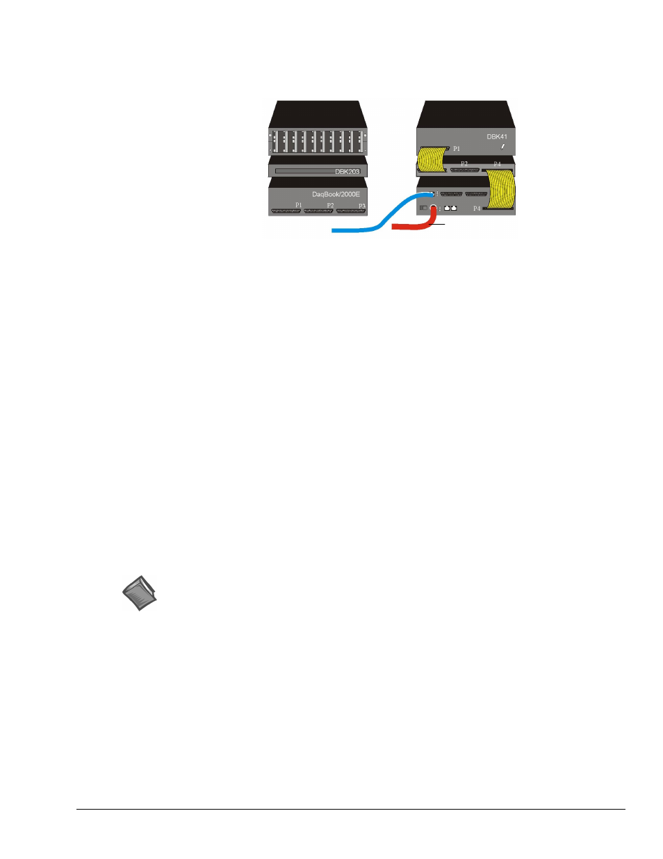
Example 2: DaqBook/2000E with a DBK41 and a DBK203
Channel Input Side Device Interface Side
DaqBook/2000E System
with a DBK41 and DBK203
Lines and Cables Used in Example 2 [Device Interface Side Only]:
1. Power Supply - To the DaqBook/2000E POWER IN DIN 5 connector, +10 VDC to +30 VDC,
typically from a TR40U power adapter.
2. From the DaqBook/2000E ETHERNET jack to a 10/100BaseT Ethernet Network or to the
ETHERNET jack on a PC. Applicable Ethernet patch cables (1.5-foot or 7-foot) are CA-242 and
CA-242-7, respectively.
3. From DaqBook/2000E’s P4 connector to the DBK203’s P4 connector, via a CA-195-1 cable.
4. From DBK203’s P1 connector to a DBK41’s P1 connector via one CA-37-1T cable.
Note 1: Information regarding the use of CA-37-T cables is provided on page E-9.
Note 2: In reference to the above figure, it is possible to connect the DBK41 module without using a
DBK203. In the scenario in which the DBK203 is not used, the DBK41 module would be
rotated 180° and then cabled to the DaqBook/2000E’s P1 connector via a CA-37-1 cable.
Reference Notes:
➣
For detailed information regarding the DBK41 10-Slot Analog Expansion Module or the
DBK203 Screw-Terminal Adapter Module, refer to the DBK Option Cards and Modules User’s
Manual (p/n 457-0905). A PDF version of the document is included on the data acquisition CD.
➣
Both the DBK Option Cards and Modules User’s Manual (p/n 457-0905) and the DBK Basics
document module include power management information. You should use the Available Power
Chart and DBK Power Requirement Worktable to calculate your system’s power needs. Doing so
will enable you to ensure that adequate power will be supplied to all system components. PDF
versions of both documents are included on your data acquisition CD.
DBK41
DBK203
(Note 2)
DaqBook/2000E
DBK41
DBK203
(Note 2)
DaqBook/2000E
To ETHERNET To POWER