Appendices, Appendix d- device connector reference, Appendix d – device connector reference – Measurement Computing DaqBook 2000 Series Installation User Manual
Page 27: Appendix d – device connector reference d, Daqbook/2000a
Appendix D
977296
Device Connector Reference D-1
Appendix D – Device Connector Reference D
For DaqBook/2000 Series Devices
DaqBook/2000A …… D-1
DaqBook/2000X …… D-3
DaqBook/2000E …… D-5
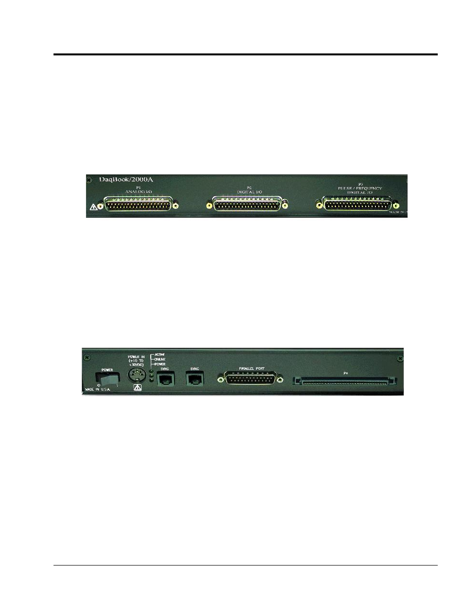
DaqBook/2000A
Front Panel
The DaqBook/2000A’s front panel offers three DB37 connectors designated as P1, P2, and P3.
P1 connects to Analog I/O.
P2 connects to Digital I/O.
P3 connects to Pulse / Frequency Digital I/O.
The DaqBook/2000 Series User’s Manual (p/n 1103-0901) includes pinouts for each.
Rear Panel
DaqBook/2000A’s rear panel contains a power switch, DIN5 power connector, LEDs, synchronization
ports, a parallel port connector, and a 100-pin (P4) connector. Additional detail follows. Items
described below are done so from left to right, when looking at the rear panel.
POWER Switch: A rocker-type switch with a “0” label for Power Off, and a “1” for Power On.
POWER IN: +10 to +30 VDC, through a socket type DIN5 connector on the chassis.
Power is typically supplied from a TR40U power adapter.
LEDs: ACTIVE – Lights when a sample has been converted by the A/D Converter.
ONLINE – Lights when software establishes communication to the unit.
POWER – Lights when power is turned on and is present.
SYNC (Qty of 2) – Two “synchronization ports” provide a means of synchronizing multiple
DaqBook/2000 Series units in regard to post-trigger scanning. The ports accept CA-74-1 and CA-74-5
RJ-11, 6 conductor type cables.
Parallel Port – A DB25 connector used to connect theDaqBook/2000A to the Parallel Port of the host
PC, or to an Expansion Port of a DaqBook/2000E, or to an Expansion Port of a WBK25 Ethernet
Interface Module. Applicable cables are CA-35-2 (2-foot) and CA-35-12 (1-foot).