Greenheck ERCH - Energy Recovery Unit with Packaged DX (468151) User Manual
Page 8
8
Energy Recovery Unit with Packaged DX
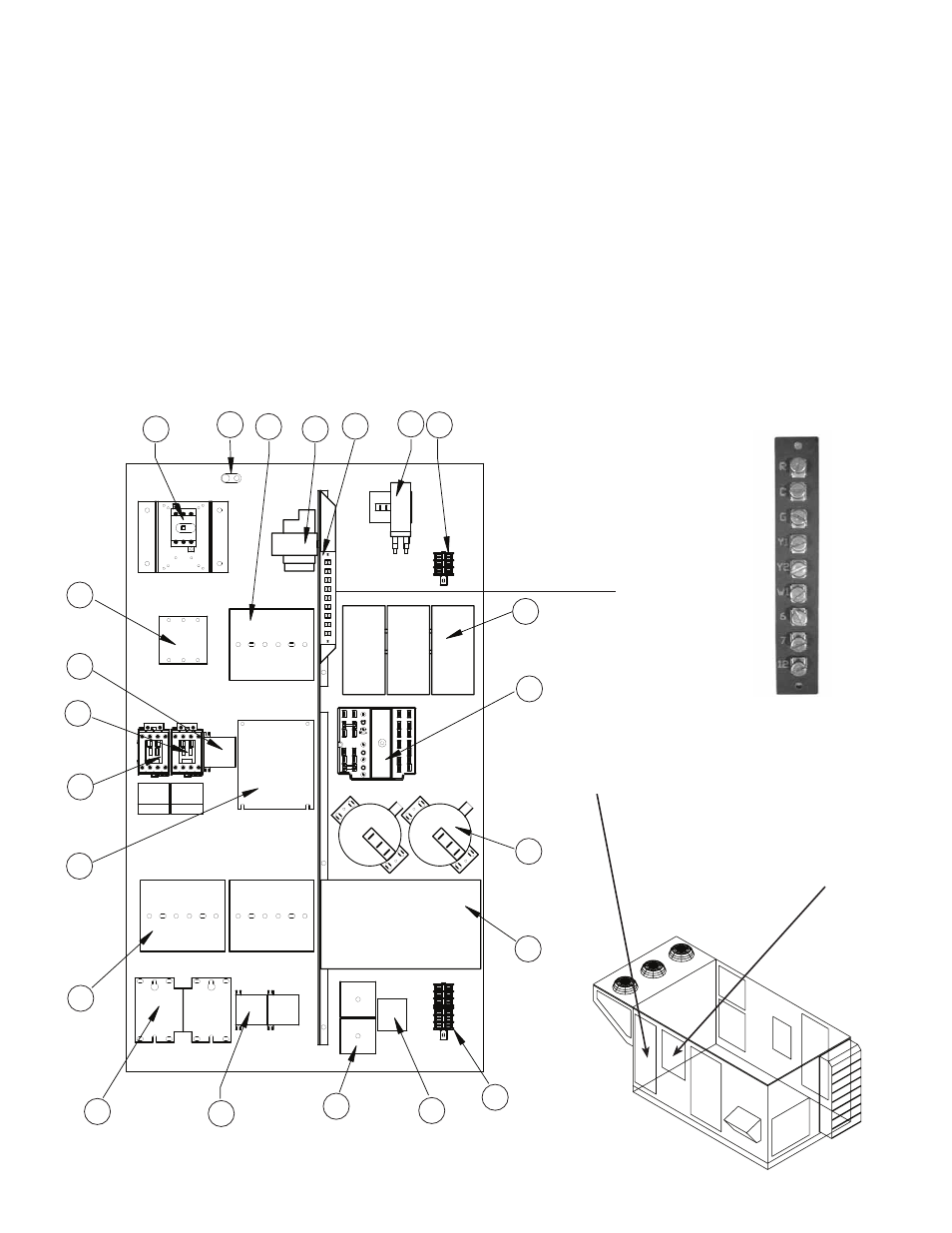
1 . Main Disconnect (non-fusible,
lockable)
2 . Motor Starter - Exhaust Air Fan
3 . Motor Starter - Outdoor Air Fan
4 . Motor Contactor - Energy Wheel
5 . 24 Vac Control Transformer
6 . 24 Vac Terminal strip
7 . Fuses for blower motors
8 . Grounding lug
9 . Distributor block
10 . Compressor fuse blocks
11 . Compressor contactors
12 . Condensing fan contactors
13 . Compressor cycle timers
14 . Compressor relay
15 . Terminal block
Optional Control Center Components
16 . DDC controller
17 . Dirty filter pressure switches
18 . Economizer module
19 . Thermostats for:
- Economizer module
- Energy Recovery wheel frost
control
- Compressor lock out
20 . Terminal block
21 . Frost control pressure switch
22 . Energy recovery wheel VFD
CONTROL CENTER COMPONENTS
If wire resistance exceeds 0 .75 ohms, an industrial-style, plug-in relay should be added to the unit control
center and wired in place of the remote switch (typically between terminal blocks R and G on the terminal strip
(refer to Typical Control Center Components) . The relay must be rated for at least 5 amps and have a 24 Vac
coil . Failure to comply with these guidelines may cause motor starters to “chatter” or not pull in which can
cause contactor failures and/or motor failures .
Note: Standard factory installed electric post-heaters have their own disconnect separate from the unit
disconnect. Thus, each electric post-heater requires its own separate power connection.
2
3
4
7
Component #6
Exploded Detail
of Terminal Strip
1
5
6
8
9
10
11
12
13
14
15
16
18
19
20
21
22
Refer to “Refrigeration
System” section for
components in compressor
compartment
17
Access to Control Center
Components is gained through
the access panel indicated .