Gasboy Hi-Flow Sat Pipng Conversion Kits User Manual
Introduction, Intended users
MDE-4514 Instructions for Installing Atlas™ Hi-Flow Satellite Piping Conversion Kits M06391K00X • June 2006
Page 1
Introduction
This document provides instructions for installing the Atlas
™
Hi-Flow Satellite Piping
Conversion Kits M06391K001 through K004.
Kit Number
Description
M06391K001
Kit, Atlas Hi-Flow w/Sat Conversion, Single Grade 1 110V
M06391K002
Kit, Atlas Hi-Flow w/Sat Conversion, Dual Grade 1 and Grade 2 110V
M06391K003
Kit, Atlas Hi-Flow w/Sat Conversion, Single Grade 1 220V
M06391K004
Kit, Atlas Hi-Flow w/Sat Conversion, Dual Grade 1 and Grade 2 220V
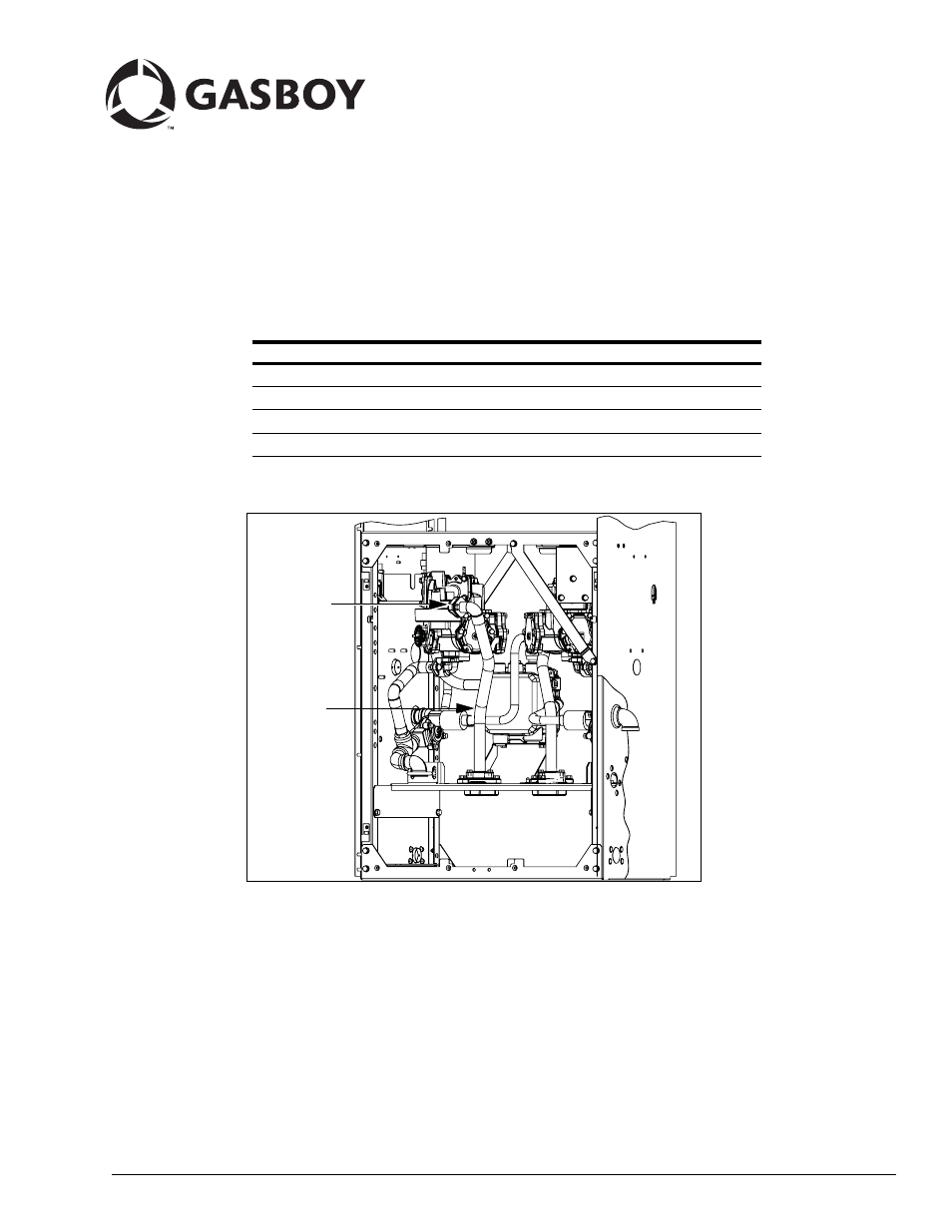
Figure 1:
Manifold Inlet
Feedline Ref
Atlas Hi-Flow with Satellite Piping Assembly
Intended Users
The intended users of this document are Authorized Service Contractors (ASCs).
MDE-4514
Instructions for Installing Atlas
™
Hi-Flow
Satellite Piping Conversion Kits
M06391K00X
June 2006
Document Outline
- Introduction
- Important Safety Information
- Installing Atlas Hi-Flow Satellite Conversion Kits M06391K001, K002, K003 and K004
- Preparing for the Installation
- 1 Close and test shear valves. Run the unit to bleed off pressure and drain the fuel into an approved container.
- 2 Request permission from the manager/owner to remove power from the unit and then remove power using normal procedures. Perform the lockout/tagout safety procedures.
- 3 Ensure that you have the proper kit for the model dispenser to be retrofitted.
- 4 Follow all applicable safety rules and procedures.
- Installing the Conversion Kits (M0639K00X)
- Removing the Existing Solenoid Valve and Discharge Line
- 1 Remove the exterior discharge fitting and any grommet. Residual pressure may exist. Wear eye protection.
- 2 Remove and retain the two screws holding the discharge casting to the bottom of the meter. Remove the discharge casting and the attached discharge piping. Collect fuel in an approved container, clean up any spills and dispose properly.
- 3 Disconnect the solenoid valve wiring in the junction box. Mark the connections in the junction box for all wires connected to the solenoid valve, so that the valve replacement can easily be connected to the correct wires.
- 4 Disconnect the feedline from the solenoid valve/filter manifold on the meter. Disconnect the valve conduit union.
- 5 Loosen but do not remove the nut holding the meter stabilizer bracket to the frame so that the bracket can be maneuvered to pe...
- Mounting the No-Valve Filter Manifold and Meter Discharge Fitting
- 1 Insert the filter strainer (R19457) into the no-valve filter manifold (M04607B005) from the kit. Push the strainer fully into the cavity so that it does not interfere with the filter boss threads.
- 2 Ensure that the meter check valve is still in place in the meter inlet, and grease the O-Rings and insert them into the groove...
- 3 Insert the feedline O-Ring into the manifold inlet and lightly grease to retain and attach the feedline. Insert and tighten the two screws.
- 4 Lightly grease the meter discharge O-Ring and insert it into the groove in the meter discharge. Ensure that the O-Ring is fully seated in the groove and is not offset by the O-Ring retainer tabs in the meter discharge.
- 5 Attach the meter discharge casting to the meter discharge and insert the two screws and tighten them.
- Modifying the Junction Box
- Discharge Line Assembly
- 1 Assemble the following parts as shown in Figure 4 using pipe sealant on the male threads:
- 2 Depending on whether you are assembling the discharge for Grade 1 or Grade 2, route solenoid coil wires through the appropriate conduit (refer to Figure 4). Grade 1 is on the left when facing the junction box.
- 3 Lightly grease the O-Ring and insert it into the groove on the meter discharge casting (refer to Figure 2 on page 7). Attach the flange on the copper tube assembly (Figure 4) to the meter discharge flange and insert two M8 x 16 screws and tighten them.
- 4 Route the valve coil wires into the junction box. Attach the conduit to the fitting in the junction box and tighten them.
- 5 Check discharge piping alignment and adjust as needed. Attach the satellite piping support bracket (Figure 4) to the dispenser inlet support plate, insert and tighten the two M8 thread forming screws.
- 6 Insert the U-bolt (Figure 4) around the pipe elbow and through the slots on the support bracket. Attach two nuts and tighten all fasteners.
- 7 Stuff a clean rag into the elbow on the top end of the discharge line and proceed to “Modifying the Side Sheathing for the Discharge” on page 10.
- Modifying the Side Sheathing for the Discharge
- 1 Mark the location of the discharge elbow on the side sheathing as shown in Figure 5 on page 11. Check the dimensions against t...
- 2 Remove the sheathing from the unit.
- 3 Using a 1-3/4 inch diameter cutter, cut a hole through the sheathing so the discharge can protrude through when completed. Deburr the hole on the sheathing.
- 4 Reassemble the sheathing to the unit.
- 5 Assemble the black painted elbow (Figure 4 on page 9) and the 1 x 1-1/2 inch nipple. Insert the grommet (Figure 4 on page 9) over the nipple. The elbow should point down.
- 6 Remove the rag from the elbow in the discharge assembly. Insert the nipple from the assembly made in step 5 through the hole c...
- 7 Rewire the solenoid valves in the junction box.
- 8 Connect the satellite piping to the elbow on the lower end of the assembly.
- 9 Insert Q10554-21 (1-3/4 inches diameter) plastic plug into the hole where the previous discharge exited the unit.
- Removing the Existing Solenoid Valve and Discharge Line
- Completing the Installation
- 1 Replace the junction box cover.
- 2 If the unit is modified on the island, inform the manager/owner that power will be restored to the unit and then restore power using normal procedures. Purge the unit of air.
- 3 Check for leaks.
- 4 Release the emergency shutoff valve.
- 5 Remove the lockout/tagout and return to normal operation.
- Preparing for the Installation