Position as shown in, Figure 2, Posi – Gasboy Totalizer Retro User Manual
Page 8
Installation
Page 8
MDE-4511B Retrofit Kits for Atlas™ Electro-mechanical and Commercial Electronic Units Installation Instructions · June 2011
7
If connecting cables on a retail unit with Pulse-out (for block diagram, see
on
a
Locate the cable (M05586A001) in the kit.
b Connect P1501 Connector to the totalizer on Side A of the unit.
c Connect P1504 Connector to the totalizer on Side B of the unit.
d Connect J202 Connector to P202 on Pump Controller PCA (T20011-G1).
e Locate the existing cable (M05108A001) connected to P2 on the power supply and
connect J804 Connector to P804 on the totalizer.
8
If connecting cables on a retail unit without Pulse-out (for block diagram, see
):
a
Locate the cable (M04889A001) in the kit.
b Connect J922A Connector to the totalizer on Side A of the unit.
c Connect J922B Connector to the totalizer on Side B of the unit.
d Connect J406 Connector to PP406 on Pump Interface PCA (T18994-G1).
e Locate the existing cable (M05108A001) connected to P2 on the power supply and
connect J804 Connector to P804 on the totalizer.
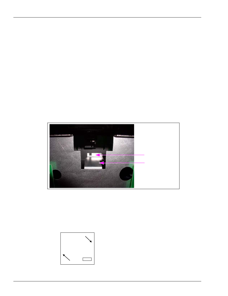
Figure 2: Mounting Position for the Electro-mechanical Totalizer
Display Support Bracket
Mounting “Shelf”
Slot in Support Bracket
Adding Decals (Dual Units Only)
Decals must be added to designate which totalizer is associated with which hose on the unit.
The totalizer on the Side A of the unit is associated with the hose on Side 1 of the unit and the
totalizer on the Side B of the unit is associated with the hose on Side 2 of the unit. The
following figure indicates the side locations:
Junction
Box
Side A
Side B
Side 1
Side 2