Unit (cpu) board (see, Figure 1 – Gasboy Totalizer Retro User Manual
Page 7
MDE-4511B Retrofit Kits for Atlas™ Electro-mechanical and Commercial Electronic Units Installation Instructions · June 2011
Page 7
Installation
3
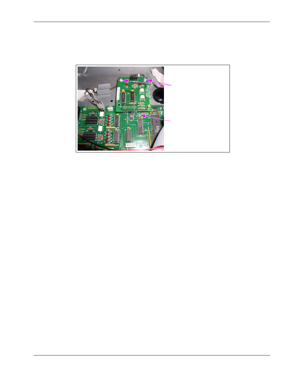
Align the two holes in the corners of the Printed Circuit Assembly (PCA) with the two
standoffs (already mounted to the shelf) and secure the board with two screws (M00417B224).
Figure 1: Mounting the Pulse-out/RS-485 Board (Commercial Unit Only)
Mounting Screws (M00417B224)
P2 and P8 Connectors
Installing the Electro-mechanical Totalizer
To install the electro-mechanical totalizer in a commercial or a retail unit and to connect the
cables, proceed as follows:
1
On the back of the bezel face at the opening for the totalizer, remove the two nuts securing the
plastic glass plate (with the black tedlar decal) using the appropriate wrench and remove the
plate.
Note: Retain the nuts for remounting.
2
If installing totalizer on a commercial unit, remove the black tedlar decal from the plastic glass
plate. Remount and secure the plate with the two nuts removed in step
.
3
Locate the Totalizer (M00455A002) in the kit and install on the display support bracket in
position as shown in
. Position the screw in the totalizer in the slot in the
support bracket (as a locator for the totalizer).
4
Secure the totalizer to the support bracket with the Cable Tie (Q10178-05).
5
If working with a dual unit, repeat steps
through
for the other side of the unit.
6
If connecting cables on a commercial unit (for block diagram, see
a
Connect the Side A (J-Box side) totalizer cable to the totalizer A (P802 Connector) on the
Pulse-out/RS-485 board.
b Connect the Side B totalizer cable to the totalizer B (P803 Connector) on the
Pulse-out/RS-485 board.
c Locate the existing cable (M05108A001) connected to P2 on Power Supply and connect
J804 Connector to P804 on totalizer.