Completing the installation, Figure 4 – Gasboy Totalizer Retro User Manual
Page 10
Completing the Installation
Page 10
MDE-4511B Retrofit Kits for Atlas™ Electro-mechanical and Commercial Electronic Units Installation Instructions · June 2011
7
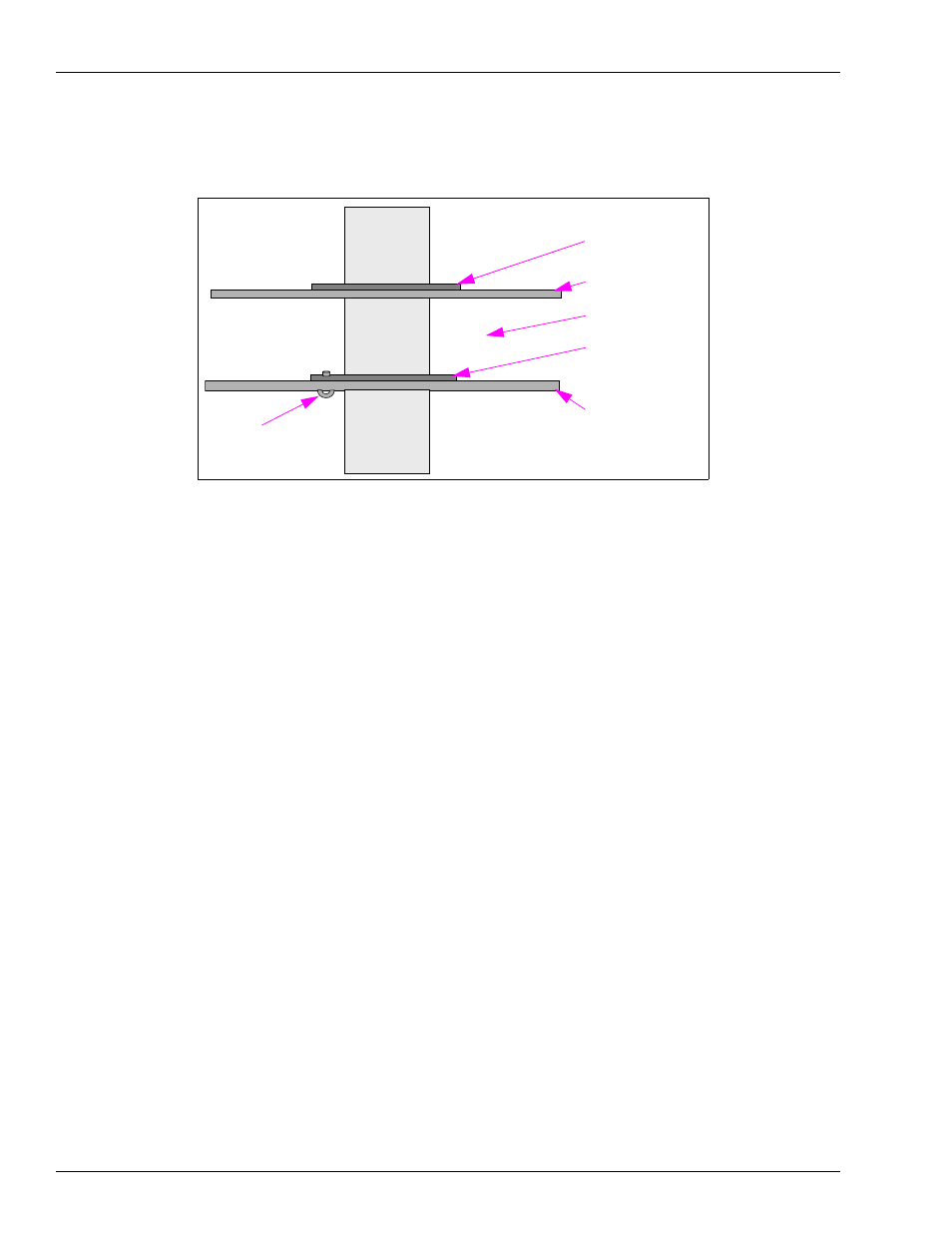
Place a washer on the conduit on the top of the upper barrier plate.
Figure 4: Routing Conduit Through Barrier Plates
Washer
Washer
Upper Barrier Plate
Lower Barrier Plate
Air Gap
Screw
(Securing Washer)
8
At the lower end of the conduit, connect to the union mounted in the junction box. Ensure that
the Cable Assembly (M05189A002) cables are properly routed into the junction box.
9
Secure the washer to the lower barrier plate using a screw (M00417B224). Place the screw
from the under side of the lower barrier plate (see
). Hold the washer securely in place
against the barrier plate when mounting and tightening the screw.
Note: There are two screw holes in the washer. However, use only one screw to secure. Place
the screw in the hole behind the conduit (looking from the Side A of the unit-side with
the junction box).
10
At the upper end of the conduit, connect the cable (M05189A001) connector to P1 on the
Pulse-out/RS-485 PCA (see
11
Place the shield (M05235B001) in the junction box and secure with the screw (M00417B113)
(see
on
).
12
Connect the four wires at the junction box.
13
Remount the junction box cover and secure with screws that were removed in step
Completing the Installation
1
After the installation is complete, proceed as follows:
a
Remount the dial enclosure assemblies using the screws removed in step
on
.
b Remount the doors on both sides of the unit.
c Secure doors with the keylocks.
2
Inform the manager/owner that the unit can be returned back to service.