FSR PATHFINDER Covers 12X8 THROUGH 32X32 User Manual
Page 25
Pathfi nder Matrix
25
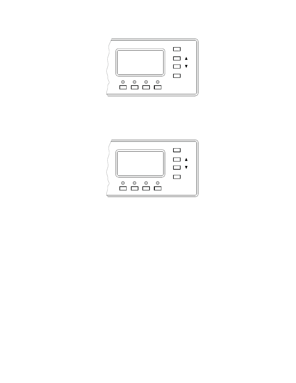
The screen will look like this:
ESCAPE
SELECT
SPLIT SETUP
A RGB
>
B RGB
C RGB
SAVE
The "A-B-C" (labeled R-G-B on the unit) designations refer to the physical location of the video
cards from top to bottom in the Pathfi nder Matrix chassis Pressing the UP and DOWN buttons will
scroll through the fi ve available confi gurations. In this example the input is set to one S-video and
one Composite video
ESCAPE
SELECT
SPLIT SETUP
A SVIDEO
*
B SVIDEO
C COMPOSITE
SAVE
Pressing SAVE will store the selected confi guration for that input. The user can then select another
input to set up, or press the ESCAPE button to return to the INPUT SETUP menu.
CABLE LENGTH (Input)
CABLE LENGTH gives the user the ability compensate for the length of cable from the source to
the Pathfi nder Matrix. The user will scroll down to CABLE LENGTH press SELECT. The user will
then use the UP and DOWN buttons to adjust the cable length from 00’to 150’ in 10 foot lengths.
When fi nished the user will press SELECT to save the setting.
NOTE: A fi nal phase adjustment of the display should be performed after cable EQ
adjustments are completed to optimize the image quality