Chapter 2 installation instructions, Front panel connector: cn41, Hdd-led connector – Foxconn 865A01-PE-6EKRS User Manual
Page 33: Reset switch, Pwr-led connector
25
Chapter 2 Installation Instructions
865A01 G/PE User Manual
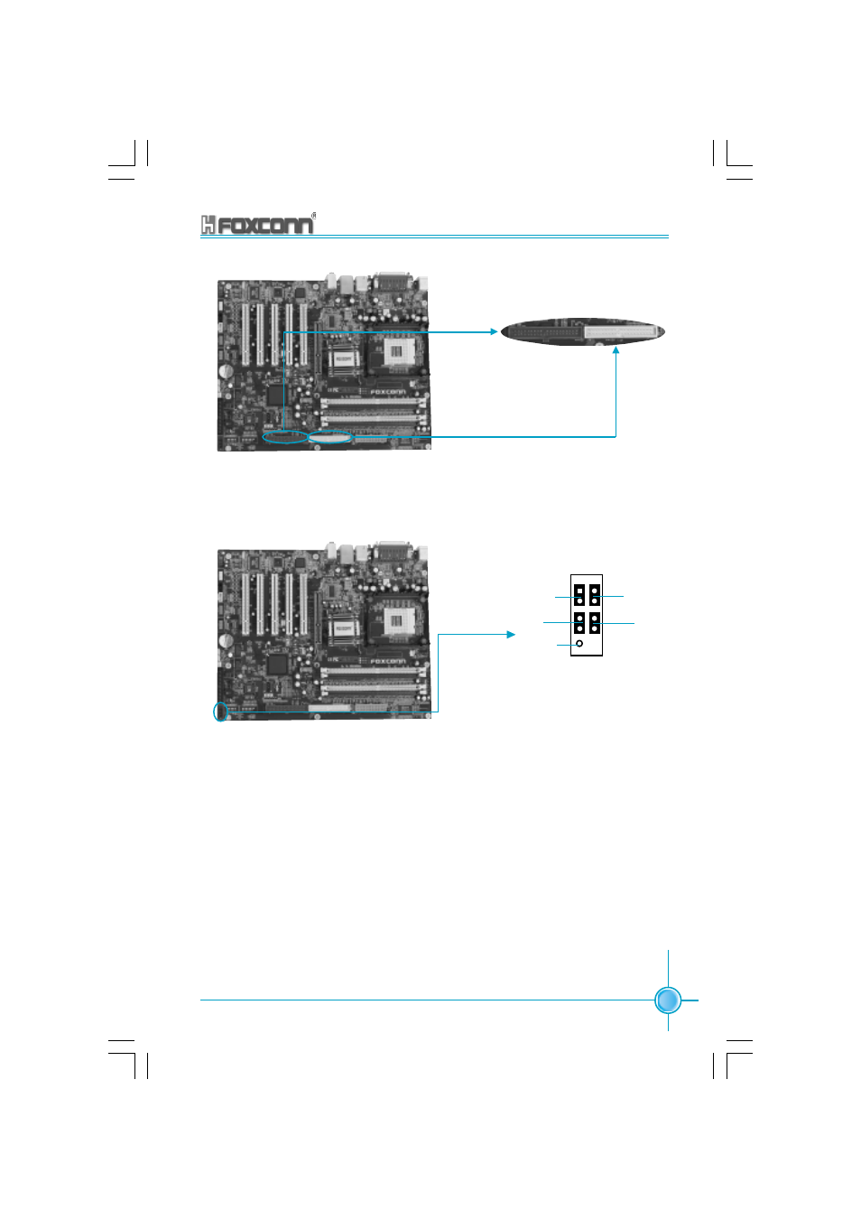
IDE2 (Secondary
IDE Interface)
IDE 1(Primary IDE Interface)
Front Panel Connector: CN41
This motherboard includes one connector for connecting the front panel
switch and LED indicator.
HDD-LED Connector
Attach the connector to the HDD-LED on the front panel of the case; the LED
will flash while the HDD is in operation.
Reset Switch
Attach the connector to the Reset switch on the front panel of the case; the
system will restart when the switch is pressed.
PWR-LED Connector
Attach the connector to the power LED on the front panel of the case. The
Power LED indicates the power supply status, and will be lit during normal
system operation. The Power LED will blink while the system is in the S1
mode, and will be turned off when the system is in either S3 or S5 mode.
NC
HD-LED
RESET
PWR-LED
PWR-SW
+
-
+ -
9 10
1 2
865A01-FOXCONN-V1.3-EN-121603.p65
2004-5-27, 18:02
25