Rs422 loop-back test (outdoor displays) -3, 1 rs422 loop-back test (outdoor displays) – Daktronics AE-3010-7.6-R,G,A User Manual
Page 63
1.1 RS422 Loop-Back Test (Outdoor Displays)
Note: Do not connect a loop-back to more than one jack at a time.
Serial Cable (W-1249)
To complete the test, the serial cable must be plugged into the signal converter. The
table below lists the pin connections when using a serial cable (Daktronics part# W-
1249).
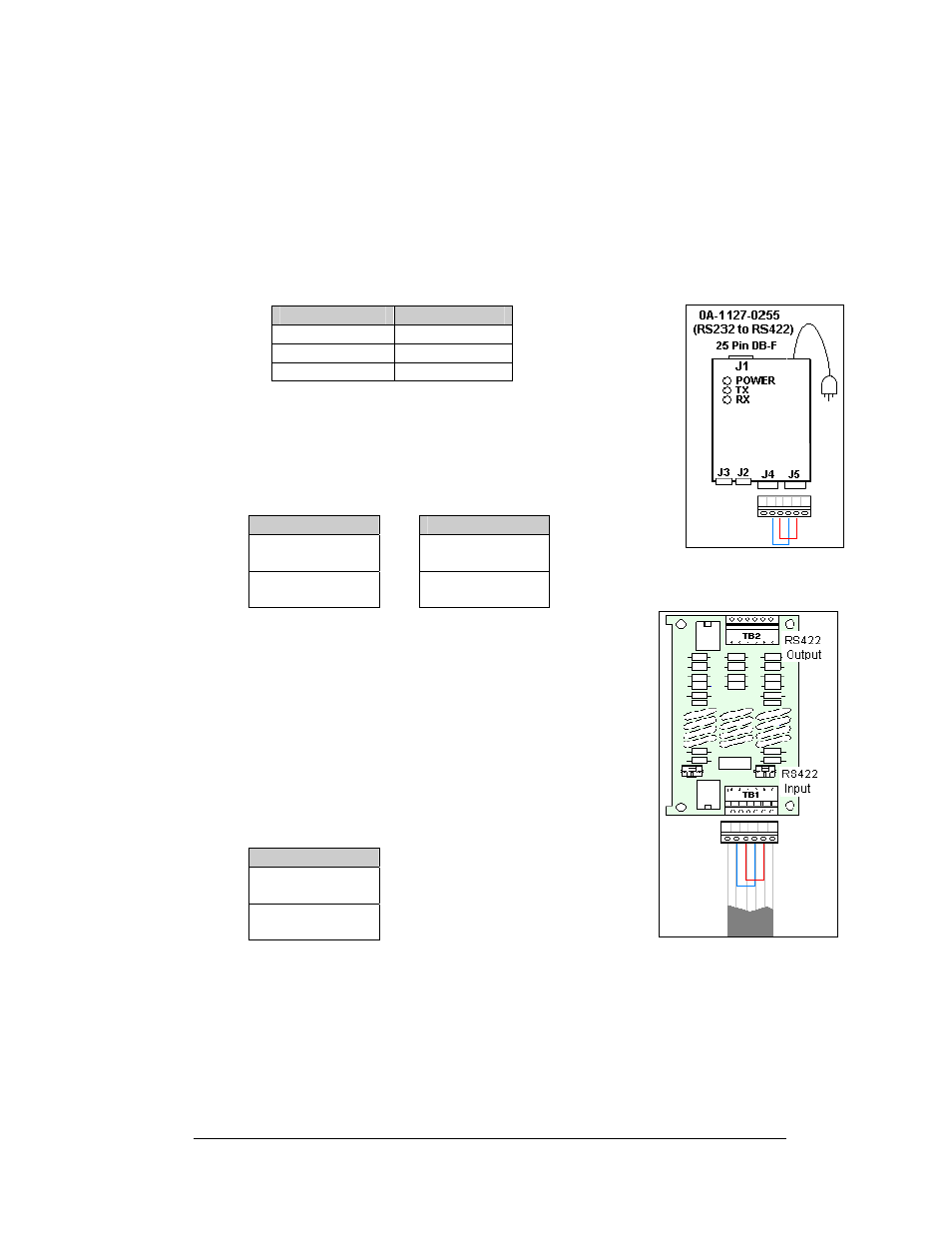
Figure 3: Jumpers at
RS232/RS422 Signal
Converter
DB9-F
DB25-F
Pin 3 – TX
Pin 2 – TX
Pin 2 – RX
Pin 3 – RX
Pin 5 – GND
Pin 7 - GND
Loop-Back Test: To perform a loop-back for testing purposes
only, use the spare plug in the signal converter and connect the
copper conductor jumpers using the following table. Refer to
. (To eliminate the display, pull out the phoenix plug with
the signal wires connected into it.)
J2 and J3
J4 and J5
(Pin 5) TX-N to
(Pin 3) RX-N
OR
(Pin 2) RX-P to
(Pin 4) TX-P
(Pin 4) TX-P to
(Pin 2) RX-P
(Pin 3) RX-N to
(Pin 5) TX-N
Figure 4: Jumpers at Surge
Board
When the wires are connected, perform the loop-back test
using the Venus 1500 software as described in Section1.4.
This test can also be done at the signal termination enclosure
on the surge board assembly, as shown in
, or, on
some displays, at the controller board input. In that case, the
wires coming from the signal converter must remain
connected, and the jumpers will be inserted along with them.
Leave the plug disconnected from the surge board while
conducting the test.
TB1 - RS422 In
(Pin 4) RX-P to
(Pin 2) TX-P
(Pin 5) RX-N to
(Pin 3) TX-N
When the wires are connected, perform the loop-back test
using the Venus 1500 software as described in Section 1.4.
Signal Converters and Loop-Back
Testing for Direct Connections
1-3