Accessing the interior of the display, Accessing the interior of the display -3, Figure 29: display interior -3 – Daktronics AE-3010-7.6-R,G,A User Manual
Page 33
Accessing the Interior of the Display
Maintenance and Troubleshooting
4-3
Remove the socket head screws from the face panel using a
9/64” Allen wrench (refer to
).
Gently pull the face panel from the body of the sign. The
display opens as shown in
. The LED module
panels can now be seen.
To access the display’s interior electronic components:
1. Disconnect Power to the display.
2. Open the face panel as described above.
3. Using a #2 Philips screwdriver, turn the screws
securing the top of the LED module panel to the
cabinet one-quarter turn counter-clockwise. (The
screws are designed to remain in the LED module
flanges, but release from the cabinet.
4. Gently tilt the LED module panel downward from
the body of the display. The panel will be
supported in a horizontal position by lanyards. DO
NOT use the module panel to support additional weight. Refer to
Figure 27: Removing the Screws
from the Face Panel
Figure 28: Display, Face Panel partially removed
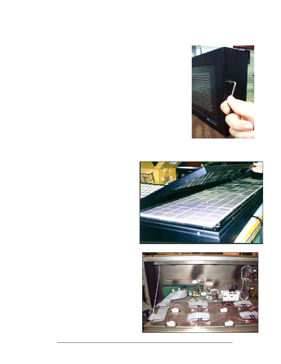
Once the LED module panel is
opened, the display interior will
be visible. Various internal
components, including the
display controller, transformer,
light detector, LED modules,
and power supplies are now
accessible for repair or
replacement.
Figure 29: Display Interior