Accessing and replacing the controller board, Accessing and replacing the controller board -5, Figure 33: power supply cable connections -5 – Daktronics AE-3010-7.6-R,G,A User Manual
Page 35: Figure 34: controller board -5
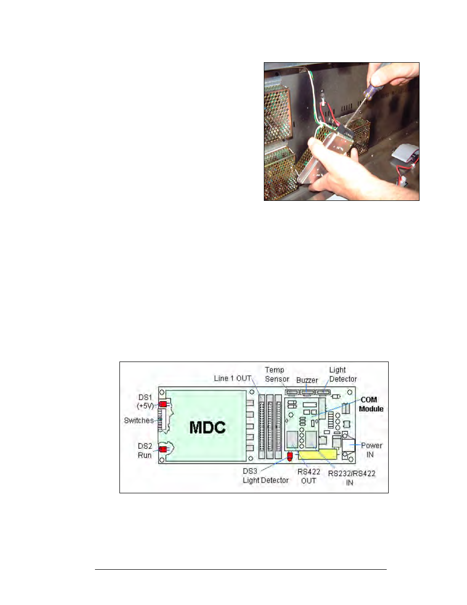
Figure 33: Power Supply Cable Connections
1. Lift the power supply and plate off the back
sheet standoffs. The metric screws securing
the power supply to the plate are now
accessible.
2. Use a #1 Philips head screwdriver to
remove the screws and free the power
supply.
3. Disconnect the power cables as shown in
.
4. The power supply is now fully released and
ready for replacement.
5. Follow the previous steps in reverse order to
reattach the new power supply.
6. Be sure to connect the power wires in the
correct locations
Refer to your display’s Schematic for the proper
wiring configuration.
Accessing and Replacing the Controller Board
The display controller is mounted to the back sheet of the cabinet in the lower left corner.
The controller receives, interprets, and activates the information from the computer to the
appropriate LEDs on the display.
The controller board includes three LEDs:
1. DS1 should be on whenever power is applied to the board.
2. DS2 should have a steady flash to indicate that the controller is running properly.
The normal rate is about once per second. The run LED will flash faster when the
controller is in test mode.
3. DS3 should flash when receiving information from the light sensor.
4. See
below for LED and connector locations.
Figure 34: Controller Board
Maintenance and Troubleshooting
4-5