Section 1 – Daktronics AE-3010-7.6-R,G,A User Manual
Page 61
Signal Converters and Loop-Back
Testing for Direct Connections
1-1
Section 1:
Signal Converters and Loop-
back Testing for Direct Connections
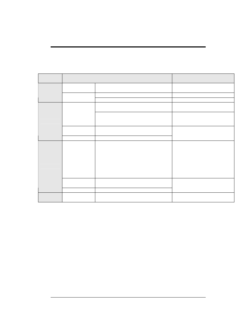
The following table gives the typical state of the signal converter when the LEDs are either on
or off. Refer to
for an illustration of the signal converters and the
locations of the various components.
LED
Indicators
Typical States
Troubleshooting
ON
Signal Converter (SC) is receiving
power
Signal Converter is not receiving power
Check power/Replace fuse
Power
OFF
Internal 1 AMP fuse is bad
Replace fuse
Signal Converter is not connected to a
serial port
Connect to open computer
COM port
On Steady
1. Serial port or serial cable is bad
2. Computer COM port is in sleep
mode
1. Try another port or replace
serial cable
2. Communicate with display
OFF Steady
Normal state, Signal Converter is not
transmitting data
TX
Brief Flicker
SC is transmitting data
ON Steady
1. Field cabling between Signal
Converter and display is bad
2. Is connected to display output jack or
terminated incorrectly
3. Bad COM port is on display controller
1. Eliminate cabling by
disconnecting wire/cable
from SC to display controller
2. Check connections and
terminations
3. Eliminate by disconnecting
wire/cable to display
controller
OFF Steady
Normal state, Signal Converter is not
receiving data
RX
Brief Flicker
SC is receiving data
TX/RX
ON Steady
(If serial cable is connected) Bad Signal
Converter
Replace Signal Converter