Display addressing, Display addressing -6, Figure 35: dip switches (address 1 shown) -6 – Daktronics AE-3010-7.6-R,G,A User Manual
Page 36
To replace a failed controller:
1. Disconnect power to the display.
2. Open the display and lift the LED module panel to access the interior
components.
3. Label all the signal cables before removing them from the controller
4. Remove all power and signal connections from the board. Pressing outward
on the tabs, and carefully pulling them from the jack releases the “Locked”
connectors.
5. Remove the #6 mounting screws. Five of the five screws are hex head,
while one is a Philips head. Remove the mounting six screws using a 3/16"
nutdriver.
6. Take note of the switch configuration and set the same address on the new
controller.
7. Carefully remove the controller board from the display.
8. Attached the new controller using the #6 screws. Be sure to replace the
Philips head screw in the location where it was removed.
9. Reconnect the power and signal cables.
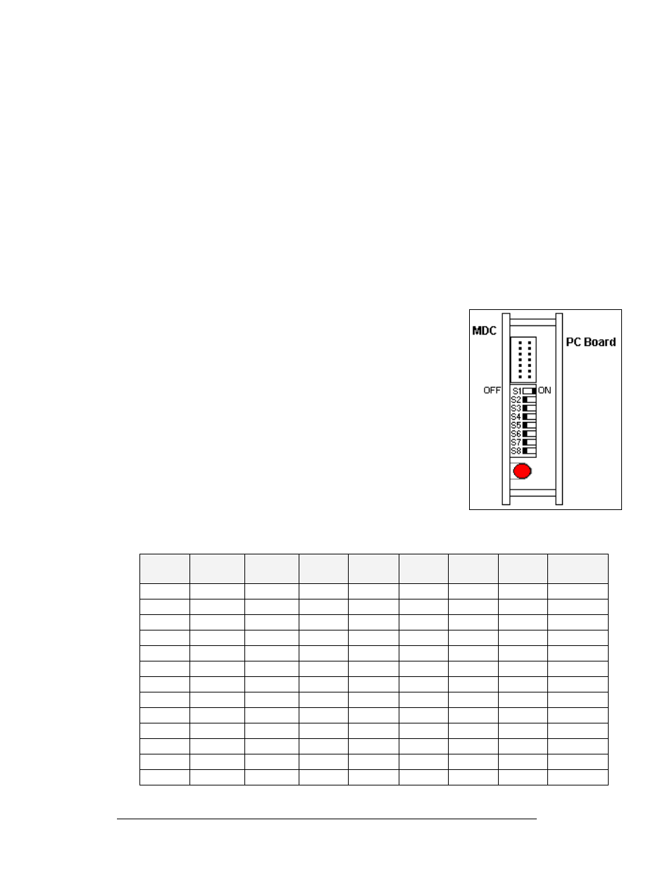
Figure 35: DIP Switches
(Address 1 shown)
Display Addressing
Before a display can be run in a sign network, it must have an
address. The display address can be set using “DIP” switches
located on a PC board known as the MDC. The MDC is the circuit
card mounted on the left end of the controller board.
Locate the DIP switches on the MDC. They should be on the
bottom end of the card. Refer to
for a picture of the DIP
switches.
When replacing a controller board, be sure to set the DIP switches
to the same address configuration as the defective controller. The
DIP switches follow standard binary code.
Note: By setting the DIP switches to address 0 (flip all the switches
up or toward the numbers on the circuit board), a test mode can be
activated. The display’s power must be turn off and then back on to
recognize test mode, or any address change.
Switch
8
Switch
7
Switch
6
Switch
5
Switch
4
Switch
3
Switch
2
Switch
1
Address
Off Off Off Off Off Off Off Off
Test
Mode
Off Off Off Off Off Off Off On 1
Off Off Off Off Off Off On Off 2
Off Off Off Off Off Off On On
3
Off Off Off Off Off On Off Off
4
Off Off Off Off Off On Off On 5
Off Off Off Off Off On On Off 6
Off Off Off Off Off On On On
7
Off Off Off Off On Off Off Off
8
Off Off Off Off On Off Off On 9
Off Off Off Off On Off On Off 10
… … … … … … … …
Off On On On On On On On 127
Maintenance and Troubleshooting
4-6