Modem, Tcp/ip or lan system, Modem -7 – Daktronics AE-3010-7.6-R,G,A User Manual
Page 27: Tcp/ip or lan system -7, Figure 23: modem system layout -7
Modem
Reference Drawings:
V1500 System Riser Diagram, Modem ......................... Drawing A-91386
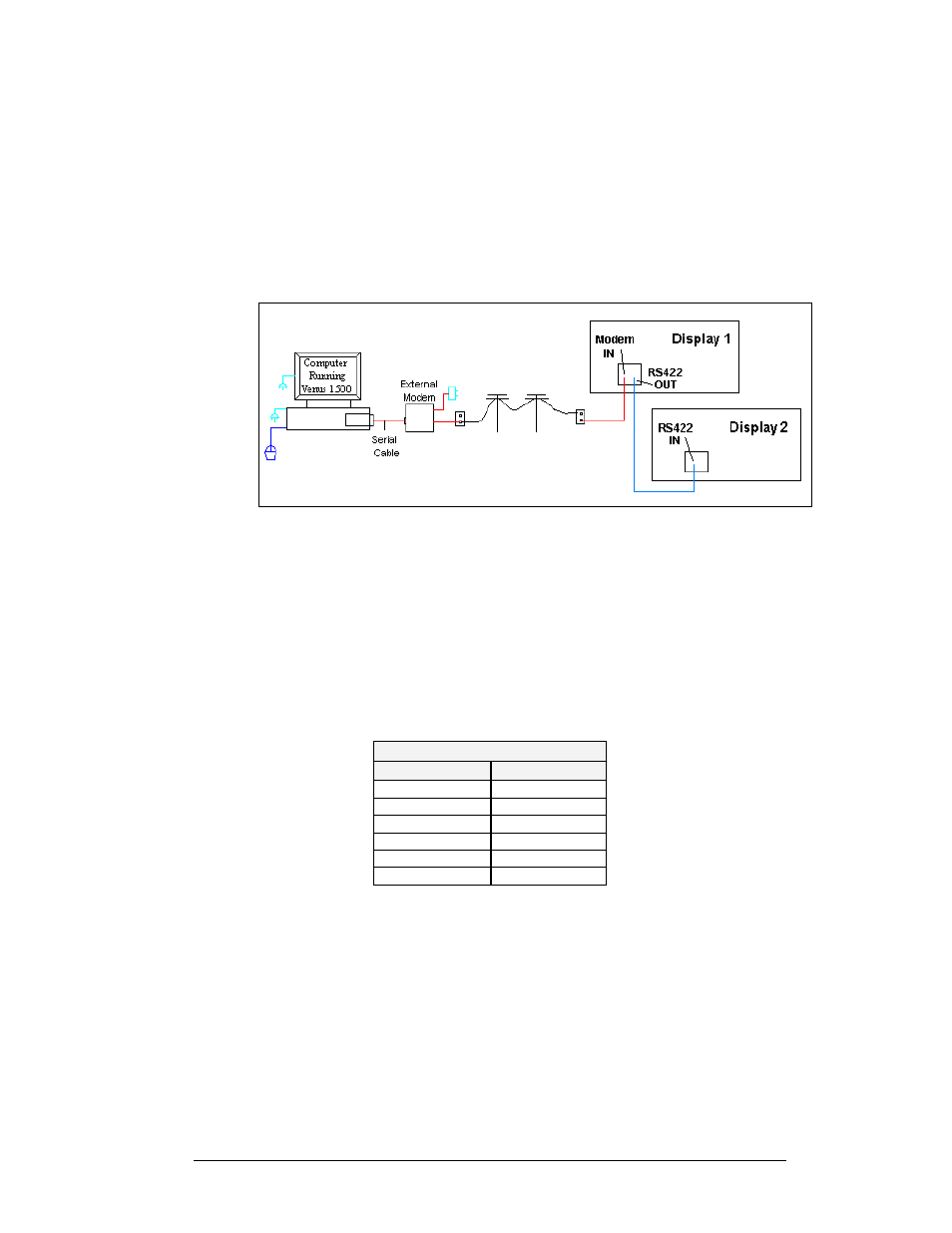
A modem system uses standard phone lines to connect from the computer to the
display. Both the modem at the computer and at the display will need to be
connected to a phone jack. Refer to Drawing A-91386 and
for the system
layout.
Figure 23: Modem System Layout
1. Modem connection:
a. If using an internal modem, connect a phone line from the
modem to the wall phone jack.
b. If using an external modem, connect the cable from the serial
port on the computer to the input on the modem, then connect a
phone line from the modem to the wall jack. Plug in the power
pack to the external modem.
2. Connect an RJ11 phone line from the wall jack to the input on the back
of the display.
3. The display requires a dedicated phone line.
Pin out of the Modem In Jack
Pin Number
Function
Pin 1
N.C.
Pin 2
N.C.
Pin 3
TIP-P
Pin 4
Ring-P
Pin 5
N.C.
Pin 6
N.C.
TCP/IP or LAN System
Reference Drawings:
System Riser Diagram, TCP/IP Network ........................... Drawing A-231373
To communicate to the display over an Ethernet network requires an Ethernet card in
the computer and a network connection to the display. Refer to Drawing A-231373
and
for system layout.
Electrical Installation
3-7