Tcp/ip network, 3 display overview, 4 component identification – Daktronics AE-3010-7.6-R,G,A User Manual
Page 12: Tcp/ip network -4, Display overview -4, Component identification -4
Introduction
1-4
TCP/IP Network
The TCP/IP protocol is an interface allowing the Ethernet network card (installed in
the operator’s computer) to communicate with the display via a Local Area Network
(LAN). Refer to Section 3 and Appendix D for additional information.
1.3 Display Overview
The Daktronics indoor LED displays have been designed and manufactured for
performance, reliability, easy maintenance, and long life. The displays consist of an
array of LED pixels. The configuration of LED pixels is dependent on the family of
LED displays.
A typical display system consists of a Windows
®
based personal computer (PC)
running Venus
®
1500 software and one or more displays. The displays are offered as
single-face units, which are single-sided stand-alone displays.
Venus
®
1500 is a software package that runs under Windows
®
98, ME
™
, NT
®
4.0,
2000, or XP Home/Professional operating systems on an IBM
®
-compatible
computer. Refer to the Venus
®
1500 controller operator’s manual (ED-13530) for
installation and operation of the Venus
®
1500 editing station.
Refer to Section 4 for the summaries of how signal and power are routed through
the displays.
Galaxy displays are graphic indoor LED displays, which are available in tri-color
(red, green, and amber) characters. Daktronics offers Galaxy displays with a 7.62
center-to-center spacing, with characters in six (6) different lengths. The Galaxy
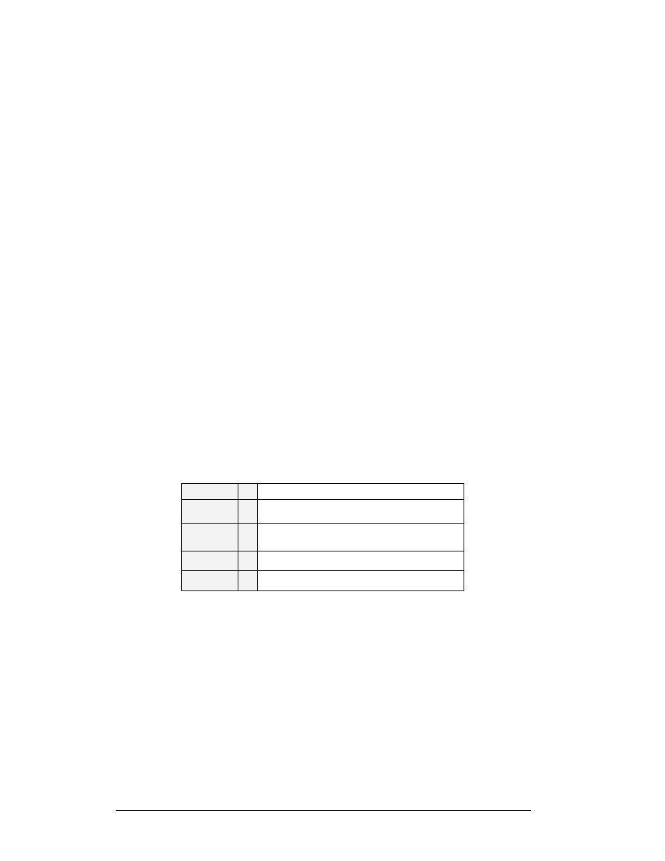
model numbers are described as follows: AE-3010-RRxCCC-7.62-TRI.
AE-3010
=
Indoor Galaxy® Display
RR
=
Number of rows high (16, 32 and 48 are
available)
CCC
=
Number of Columns Long (96, 128, 160,
192, 224 and 256 are available)
7.62
=
7.62mm center-to-center pixel spacing
TRI
=
Tricolor (red, green and amber)
1.4 Component Identification
The following illustrations depict some of the more commonly accessed Galaxy sign
components. Because Daktronics occasionally alters standard design to meet
customer needs, the actual sign design may vary slightly from the illustrations listed.
This is only a brief overview. Refer to Section 4 for more detailed information on
maintaining and troubleshooting various sign components.
Controller: The display’s controller is the “brains” of the display. The controller
receives, translates, and activates the signal information from the control computer
to the appropriate pixels on the sign accordingly.