2 control cable categories, Cable types, Control cable categories -2 – Daktronics AE-3010-7.6-R,G,A User Manual
Page 22: Cable types -2, Figure 13: phoenix-style connector -2, Figure 14: mate-n-lok connector -2, Figure 15: 6-conductor rj11 connector and cable -2
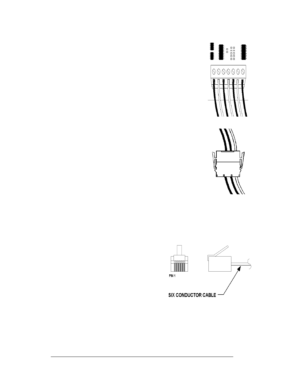
3. Phoenix
™-Style Connectors:
Phoenix-style connectors, which are usually green, are used
for the external temperature sensor termination to the
display. Refer to
. Strip one-quarter inch of
insulation from the wire prior to termination. To remove a
wire, turn the above screw counter-clockwise to loosen the
connector's grip on the wire. To insert a wire, push the bare
wire into the connector, and turn the above screw clockwise
to lock the wire into place.
Figure 13: Phoenix-
Style
Connector
Figure 14: Mate-n-
Lok Connector
4. Mate-n-Lok
™ Connectors:
The Mate-n-Lok connectors found in the signs are white and
come in a variety of sizes.
illustrates a four-pin
Mate-n-Lok connector. To remove the plug from the jack,
squeeze the plastic locking clasps on the side of the plug and
pull it from the jack.
5. Phone Jacks (RJ11/RJ45 Connectors):
RJ11 and RJ45 connectors are similar to the telephone and
network connectors found in homes and businesses cables.
In order to remove this plug from the jack, depress the small
clip on the underside of the plug. Before replacing an RJ
connector, spray it with DeoxIT
™
contact cleaner to remove
any foreign matter that may cause signal problems. In
addition, apply a generous amount of CalLube
™
protector
paste to the plug before inserting it into the jack. This paste
will protect both the plug and the jack from corrosion.
3.2 Control Cable Categories
Cable Types
The conductor connector used in the network is an industry standard, 6-pin RJ11.
This connector can be found on many
telephones and LANs.
Figure 15: 6-Conductor RJ11 Connector and
Cable
The cable used in the network is a standard flat
six-conductor telephone cable (standard flipped
cable). Refer to
. This cable has one
end that is the mirror image of the other end (i.e.
the cable is flipped). Refer to
for a
standard flipped cable.
Electrical Installation
3-2