Section 3: electrical installation, 1 common connectors in the sign, Section 3 – Daktronics AE-3010-7.6-R,G,A User Manual
Page 21: Electrical installation -1, Common connectors in the sign -1, Figure 11: ribbon cable connector -1, Figure 12: termination block -1
Section 3:
Electrical Installation
Only a qualified individual should terminate power and signal cable within this
Daktronics sign.
The Daktronics engineering staff must approve any changes made to the sign. Before altering
the sign, submit detailed drawings for the proposed modifications to the Daktronics
engineering staff for evaluation and approval, or the warranty will be rendered null and void.
3.1 Common Connectors in the Sign
The power and signal connections in the signs use several different types of
connectors. Take special care when disengaging any connector so as not to damage
the connector, the cable or the circuit board.
When pulling a connector plug from a jack, do not pull on the wire or cable; pull on
the jack itself. Pulling on the wires may damage the cable and connector.
The following information presents some common connectors encountered during
sign installation and maintenance:
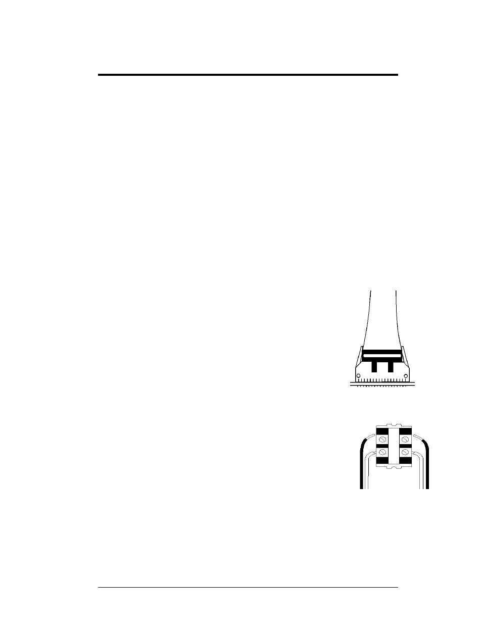
1. Ribbon Cable Connectors:
illustrates a typical ribbon cable connector. To
disconnect the ribbon cable, push the plastic clips on the
sides of the jack inward.
Before replacing a ribbon cable connector, spray it with
DeoxIT
™
contact cleaner to remove any foreign matter that
may cause signal problems. In addition, apply a generous
amount of CalLube
™
protector paste to the plug before
inserting it into the jack. This paste will protect both the
plug and the jack from corrosion.
Figure 11: Ribbon
Cable Connector
2. Termination Blocks:
Termination blocks are usually used to connect internal
power and signal wires to wires of the same type coming
into the sign from an external source. Power wires need to
have one-half inch of insulation stripped from the end of
the wire prior to termination. Tighten all screws firmly to
ensure a good electrical connection. Refer to
.
Figure 12: Termination
Block
Electrical Installation
3-1