Cybex 55620H Modular User Manual
Page 90
D. For Tandem and Modular configurations, locate four SHCS .50-13 x 1.25 (#59), four split
lockwashers .50 (#87) and four hex nuts .50-13 (#64). See Figure 7 (hardware pack).
E. For the Tandem configuration, using the hardware located in step 4D, attach both columns to
frame as shown in the Tandem Center Post & Dome Installation instruction sheet.
NOTE: The generic column shown in the Tandem and Modular instruction sheets will slightly
differ in appearance than the Leg Extension/Leg Curl Column (an angle bracket is used
instead of a tube).
F. For the Modular configuration, using the hardware located in step 4D, install angle braces
onto each column. See the exploded-view diagram shown in the Modular Center Post
Installation Instruction sheet.
5. Install the Leg Extension/Leg Curl Assembly to the appropriate configuration (see steps 5A -
5F and Figures 10 - 12B).
A. Locate the Leg Extension/Leg Curl assembly and hardware pack.
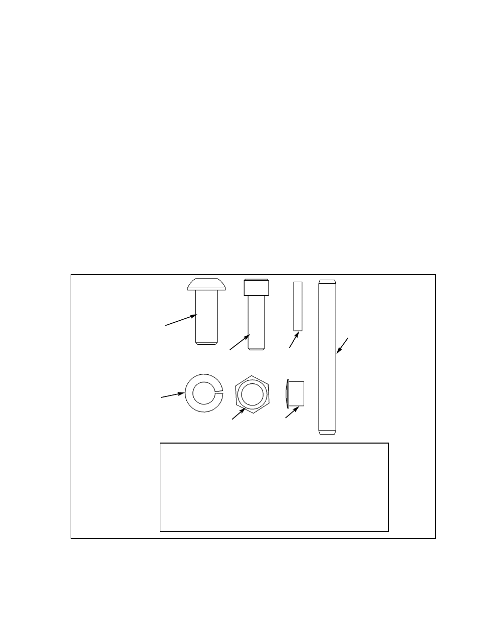
B. Verify contents of hardware pack. See Figure 10.
Figure 10
38
1
HP286819
Spiral Pin
39
1
8640-330
Spring Pin 10 mm x 90 mm Black
60
2
JC780420
BHSCS .50-13 x 1.25
61
2
PN660201
Hole Plug
64
2
HN784000
Hex Nut .50-13
87
2
JS388300
Split Lockwasher .50
90
2
JC702820
SHCS .375-16 x 1.25
ITEM QTY PART NO. DESCRIPTION
87
39
60
64
38
64
61
Cybex Modular Owner’s Manual
Page 4-36