1 switch power on, 2 led indicators – Comtech EF Data MBT-5003 User Manual
Page 42
MBT-5003 L-Band Up/Down Converter System
Revision 1
Front Panel Operation
MN-MBT5003
5–2
5.1.1
Switch Power On
Prior to turning power on to the unit, check to ensure that installation is
complete, and verify that the MBT-5003 is connected to the proper prime power
source, RF Input, and RF Output.
For more information, refer to Chapter 2. INSTALLATION and Chapter 3.
EXTERNAL CONNECTORS.
Switch on the unit and verify that the cooling fan is operational, the LED indicators illuminate as
expected, and the Vacuum Fluorescent Display is readable.
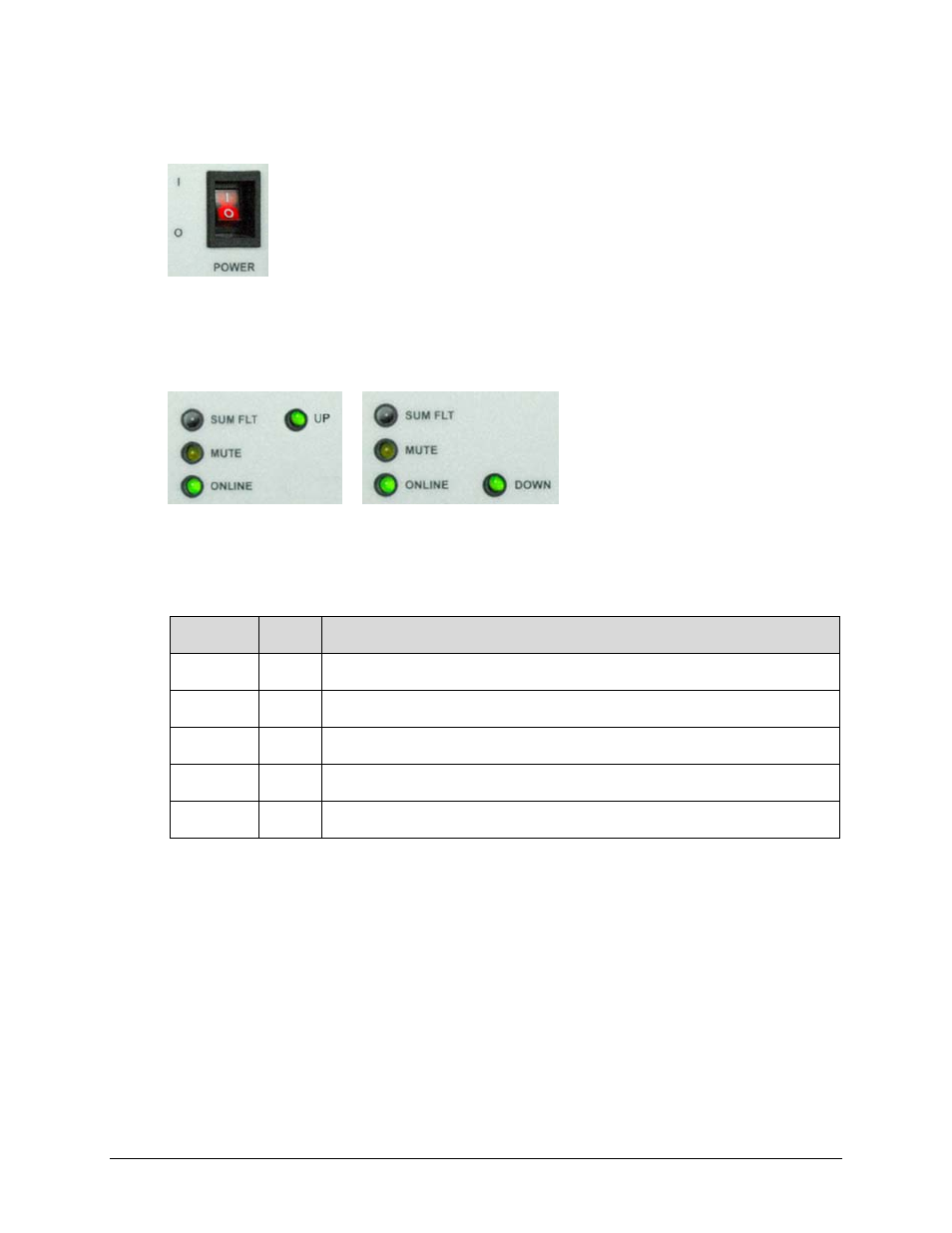
5.1.2
LED Indicators
MBT-5003-XUR MBT-5003-XDR
Unit A / Unit B LED Array Unit A / Unit B LED Array
The following table defines the operational condition, when lit, of the front panel LED indicator
arrays (four LEDs each per Units A and B, as depicted above):
LED
Color
Operational Condition (When Lit)
SUM FLT
Red
The designated unit has active faults.
MUTE Amber The designated unit is in Mute Mode.
ON LINE
Green
The designated unit is operational when lit.
UP Green
(MBT-5003-XUR only) The designated unit is operating as an Up Converter when lit.
DOWN Green (MBT-5003-XDR only) The designated unit is operating as a Down Converter when lit.