Comtech EF Data RCS10 User Manual
Page 223

RCS10 Redundant Communication System
Principles of Operation
TM058 - Rev. 2.3
Page 5-7
MASTER
OSCILLATOR
TX IF REFERENCE
RX IF REFERENCE
INT CLK
EXT IF
REF
EXT CLK
MODULATOR CLOCK
SCR
SCT
EXT CLK
RCV BUFFER
BUFFER CLK
RCV CLK
FROM DEMOD
SCR
TX CLK MUX
BUFF CLK MUX
SCTE
SCTE
PLL
PLL
DEJITTER
FIFO
TX TERR
DATA
RX TERR
DATA
RCV DATA
TX DATA
SCT
BNC EXC
BAL EXC
EXT CLK
SCR
INT CLK
SCT
AUTO
PHASE
Rx CLK
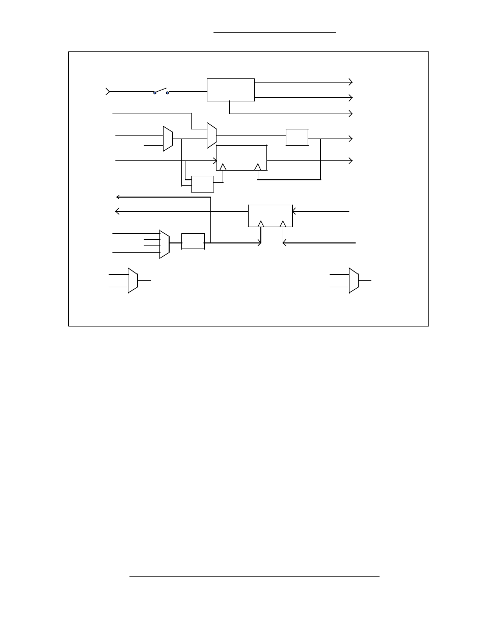
DMD10 Clock Logic
If SCTE is selected, then SCTE must be supplied to the modem. The Tx CLK PHASE should be set
to AUTO.
G.703 Interface
If the G.703 interface is selected, then the Tx clock source must be set to SCTE and the TX CLK
PHASE should be set to AUTO.
Receive Timing
Any of the selections, SCTE, SCT, EXT CLK, or SCR may be selected as the buffer clock. Data will
be clocked out of the buffer at the data rate synchronous, to selected clock source.
Loop Timing
If loop timing is desired i.e., the modem timing is slaved to the far end master station, the modem
clocks can be configured as follows:
Transmit
RS-422 or V.35 Interface
Set SCT Source to SCR. The Tx terminal equipment should clock the TX data with the SCT clock
and return data and SCTE (Optional). If SCTE is returned to the modem from the terminal equipment
set TX CLK to SCTE. If SCTE is not returned to the modem, set TX CLK to SCT.
