Comtech EF Data CDM-840 User Manual
Page 219
CDM-840 Remote Router
Revision 2
Appendix E
MN-CDM840
E–7
E.5
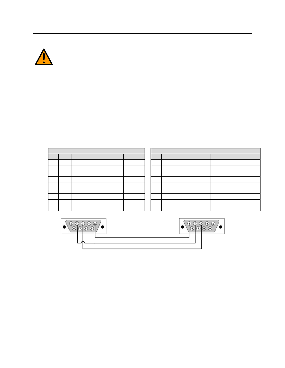
Serial Adapter Cable Fabrication Specifications Reference
CAUTION: To ensure proper operation, fabrication of this Serial Adapter Cable requires that :
•
You must wire the connectors using the pinout tables and diagram provided here.
•
Type 'D' connectors must have back-shells with continuous metallic shielding.
•
Type ‘D’ cabling must have a continuous outer shield (either foil or braid, or both). The
shield must be bonded to the connector back-shells.
Description: PC Serial Port Interface
User PC Interface End
Cable Connector Type: D-Subminiature DB-9F
(Type D-Sub 9-pin Female)
Use: For connection to the User P C R S-232 Serial
Port
Description: CDM-840 ‘CONSOLE’ Port Interface
CDM-840 Onsite Unit Interface End
Cable Connector Type: D-Subminiature DB-9M
(Type D-Sub 9-pin Male)
Use: For connection t o the CDM-840 O nsite Unit
‘CONSOLE’ Port
WIRE LIST / PINOUT
WIRE LIST / PINOUT
PIN SIG NAME
DTE (PC) PIN ASYNCHRONOUS
SYNCHRONOUS
1 DCD DATA CARRIER DETECT
IN
1 GROUND
GROUND
2 RXD RECEIVE DATA
IN
2 RS-232 Rx DATA OUT
RS-232 Rx DATA OUT
3 TXD TRANSMIT DATA
OUT
3 RS-232 Tx DATA IN
RS-232 Tx DATA IN
4 DTR DATA TERMINAL READY
OUT
4 --
RS-232 Rx CLOCK OUT
5 GND SIGNAL GROUND
--
5 --
RS-232 Tx CLOCK OUT
6 DSR DATA SET READY
IN
6 RS-232 Tx DATA ‘B’ IN
--
7 RTS REQUEST TO SEND
OUT
7 RS-232 Tx DATA ‘A’ IN
--
8 CTS CLEAR TO SEND
IN
8 RS-232 Rx DATA ‘B’ OUT --
9
RI RING INDICATOR
IN
9 RS-232 Rx DATA ‘A’ OUT --