B.3 card reset architecture, Figure b-4, Card reset diagram – Artesyn PCIE-8120 Installation and Use (July 2014) User Manual
Page 59: Card reset architecture, Pcie-8120 hardware description
PCIE-8120 Hardware Description
PCIE-8120 Installation and Use (6806800R89C)
59
B.3
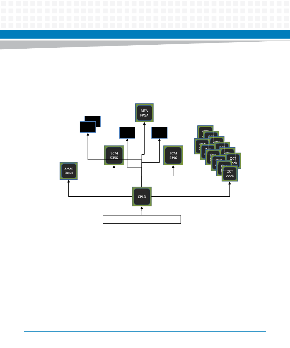
Card Reset Architecture
The following figure provides an overview of the Card Reset Architecture of PCIE-8120:
All devices on the card that provide a dedicated reset input are connected to the CPLD to allow
for individual reset control at start up or during runtime via host control. The PERST_N signal is
propagated to the ethernet network devices (NIC, Switch, PHY) to make the card behave like a
standard NIC card. All other functions are kept in reset state and released only on S/W driver
activity to allow for correct set up before going active (i.e., Switch/PHY configuration, MFA
startup, DSP boot loading).
For additional information on CPLD, refer to Logic Design Specification PCIE-
8120.2012.1206874M02A listed in
Table "Related Specifications" on page 91
.
For timing requirements on PERST# signal, refer to PCI Express Card Electromechanical
Specification Rev.2.0.2007.PCISIG CEM 2.04/11/2007 listed in
Table "Related Specifications"
Figure B-4
Card Reset Diagram
PHY
88E1512
PCIe x4 card-edge connector
PHY
88E1512
PHY
88E1111
PHY
88E1111
12x DSPx-RST_N
PERST_N
PERST-82580_N
MSW-RST_N
VSW-RST_N
2x ETH1/
2-
RST_
N
MF
A1
-RST
_N
Hard/
Auto
-RST
_N
MF
A2
-RST
_N