X-y coordinate grid (a) autodetect video input, X-y coordinate grid, A) autodetect video input – Pointmaker CPN-5800 User Manual
Page 112
Page 106 -
Pointmaker CPN-5800 Color Video Marker
Pointmaker LLC
Overview
Section Six:Using RS-232 Commands
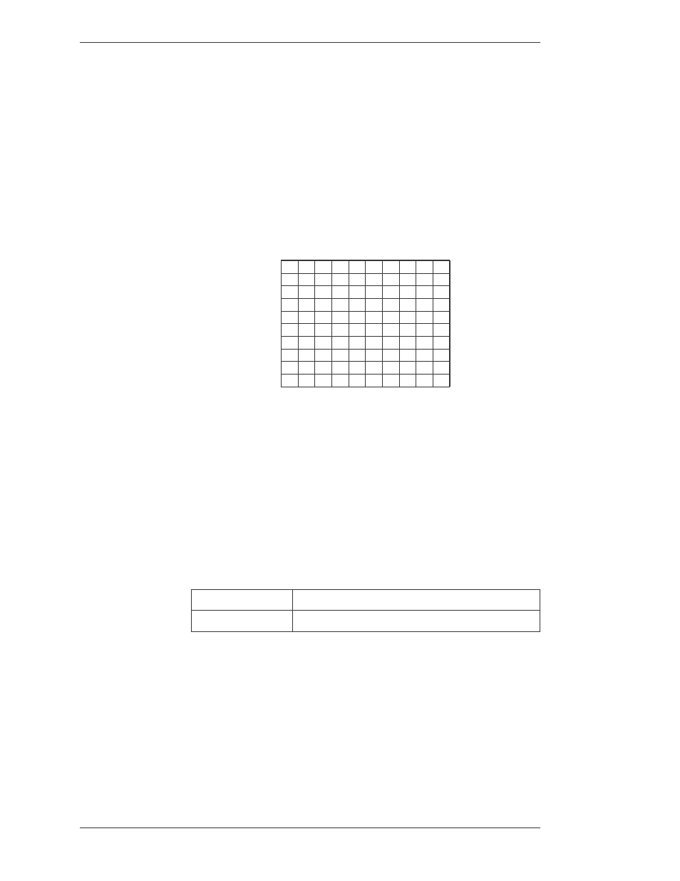
X-Y Coordinate Grid
Numerous commands refer to a screen grid with coordinates based on an inter nal
grid that is 2Ø48 x 2Ø48 units. The grid can be absolute, covering the entire
screen area, or relative to a current position. The absolute grid coordi nate of
ØØØØØØØØ is at the upper-left of the screen. The grid coordinate of
2Ø472Ø47, then, is in the lower-right. Relative grid coordinates can include
negative numbers to indicate positions above or left of a current position. In the
illustration below, XXXX = a numeric value for the horizontal axis. YYYY = a
numeric value for the vertical axis.
(ØØØØ,ØØØØ)
(ØØØØ,2Ø47)
(2Ø47,ØØØØ)
(2Ø47,2Ø47)
<--- X axis --->
<---
Y axis --->
Figure 6-1: Screen Grid
(A) Autodetect Video Input
The “A” command tells the Pointmaker whether to automatically detect what
video input to switch to.
Enables Autodetect
Disables Autodetect
NOTE: The Autodetect command is overridden by the Video Input Type (M)
command.