Casella CEL CEL-368 User Manual
Page 48
3.
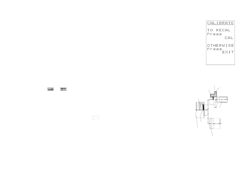
With the CEL-368 and CEL-282,
carefully fit the CEL-4725 Microphone Coupler supplied with
calibrator over the end of the microphone/preamplifier unit (Fig-
ure 7), making sure it is correctly seated against the shoulder in
the coupler cavity.
4.
Fit the calibrator into the coupler, again making sure the coupler
is firmly seated against the shoulder in the calibrator cavity.
5.
Switch the calibrator ON.
When used with these noise meters at standard temperature and
pressure, both CEL calibrators emit a 1 kHz signal at 114.0 dB,
so the display should indicate 114.0 dB (or 94 dB when the MK-
301 is fitted).
For altitude and environmental information, refer to the calibrator
instruction card.
6.
If necessary, use
and
to adjust the displayed sound
level to 114.0 dB (or to 94 dB when the MK-301 is fitted).
As the level change produced by one press of the keys is smaller
than the 0.1 dB resolution of the display, more than one press
may be required to produce a visible change. These keys have
an auto-repeat function when held down.
7.
When the indicated calibration level is correct, press
to
complete the calibration sequence.
The instrument is ready for operation using the parameter settings
that are now being shown on the SETUP menu.
To use these settings or to check the batteries, proceed to
Section 6.1 - Routine Operations.
To change the settings, refer to Section 6.3 - Setting Instrument
Parameters and Section 6.4 Setting Measurement Parameters.
EXIT
Figure 7: Fitting acoustic
calibrators
Microphone &
Calibrator
'O' Ring
Shoulder
'O'-Ring
Microphone
Shoulder
Preamplifier
Microphone/
Preamplifier Unit
Type 2 Instruments
Type 1 Instruments
900108
CEL-284/2
or CEL-282
Coupler
Page 44 - CEL-268/368 Operator's Handbook