Casella CEL CEL-480 User Manual
Print on a3
Preparation
DO NOT attempt to power from an external source
without first consulting Section 1.8 of the handbook.
Install 4 x AA size batteries in the compartment in the
underside of the unit.
Screw the Type 1 microphone finger-tight on to the
preamplifier.
Connect the Type 1 preamplifier plus microphone or the
Type 2 microphone/preamplifier assembly by inserting it
into the socket in the top of the instrument case with
the red dot facing the front to ensure correct pin location.
Menus & Control
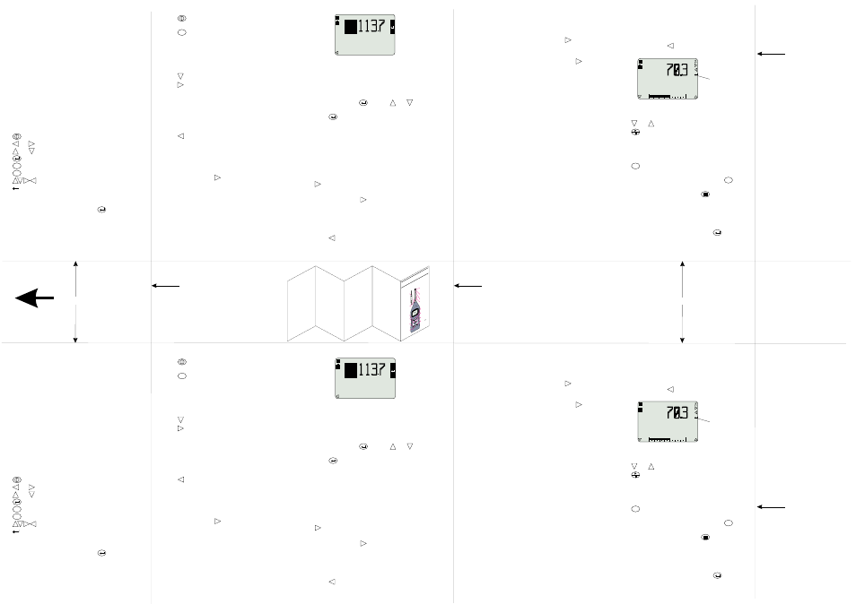
All operations are based upon a series of menus
arranged as shown in the figure.
A combination of function keys and navigator keys on
the front panel are used to move around the menu
system and implement commands. The functions are as
follows.
Power on/off.
and
Move the highlight around the options.
and
Change the contents of a field.
Enable/Disable Quick Edit.
Display Main menu (may require several presses).
Accesses data screens.
On screen show active keys.
Shows that Quick Edit mode is available.
Menu options are implemented in two ways.
1.
Leave the required option highlighted.
2.
Use the quick edit function (press
to activate)
to change the option.
Configuring the Instrument
The instrument configuration specifies how the
instrument communicates with the operator and via the
RS232 interface.
MENU
DATA
Press
to switch the instrument on and obtain the
Calibration Check screen.
Press
twice to see the Main menu which gives
access to further menus that select Measurement
Mode, Setup, Calibration, Data Recall from Memory and
Configuration.
A message such as 2/6 at the bottom of a screen
indicates that the second of six possible options is
highlighted.
Press
to move to Configure.
Press
to see the configuration menu.
Make choices about the RS232 Communication Baud
rate, Menu Language, Backlight operation and
Microphone Response (Free Field or Random) as
appropriate by leaving the required choice highlighted on
the screen.
The instrument Time and Date can also be set from the
Configuration menu.
Press
(several times) to return to the Main menu.
Calibration
Calibration ensures that the instrument is measuring
noise accurately. The Calibration menu is displayed at
the end of the self test sequence.
If Scale is mentioned, move to the Main menu, select
Calibration, then press
to see the Calibration menu.
Insert the 1/2" microphone far enough into the calibrator
cavity to be in contact with the shoulders in the cavity.
Insert the 1/4" microphone far enough into the coupler
cavity to be in contact with the shoulders in the cavity
and the microphone plus coupler far enough into the
calibrator cavity also to be in contact with the shoulders.
Avoid distorting the calibration volume by supporting the
calibrator and sound level meter on a horizontal surface.
Switch the calibrator on.
MENU
Depending on the microphone type and the response
set, the display should show one of these levels.
Microphone
Response
Calibration Level
1/2"
Free Field
114.0 dB
1/2"
Random
113.8 dB
1/4"
Free Field & Random
113.6 dB
If it does not, press
then use
and
to adjust
the display to the correct value.
Press
to save the calibration.
Select Mode
The measurement mode specifies the bandwidth to be
used for measurement. With a CEL-480, the mode also
specifies how measurements will be timed.
Either select a measurement mode, or use a pre-stored
setup (see below).
Instruments with only broadband measurement have no
Mode option.
In the Main menu, move to Mode (if available) and press
to see the Mode menu.
Select a bandwidth for use by highlighting it.
On a CEL-480 press
again to see a Timers menu for
the bandwidth that gives the option of switching the
Timers Off, setting a Duration Timer or setting a Delay
Timer.
Make choices as appropriate by leaving each one
highlighted on the screen.
Press
(several times) to return to the Main menu.
Select Setup
The Setup specifies the particular parameters that are to
be measured.
In the Main menu, move to Setup and press
to see
the Setup menu.
Select a setup for use by highlighting it.
When a setup is to be prepared and saved, press
to
move to a setup options menu.
This allows the following measurement parameters to
be specified (when available).
Mode: Broadband,
Octaves,
Third-octaves.
The following broadband parameters can be specified
(when available).
SLM Response:
RMS-, time- and peak-weightings, plus
energy exchange rate Q.
Measured Functions:
Up to 14 parameters.
Dose Results:
Threshold, for including values in calculation
Normalisation period, allows results from
different durations to be compared.
Period Results (CEL-480 only):
Interval between measurements,
Intervals for up to 2 profiles.
The following narrowband parameters can be specified
(when available).
Measured Functions:
Up to 3 functions.
Frequency Scanning Mode:
Manual, the user judges when the level is stable,
Auto, the SLM determines when the level is
stable,
Timed, measurements are taken at user pre-set
intervals,
Repeat, on the CEL-480 auto and timed scans
can be repeated automatically at user pre-set
intervals.
Broadband Measurement
From any menu press
several times until a broad-
band measurement screen is displayed.
Broadband measurement screens show one principal
and four secondary parameters that can all be changed
by the quick edit function.
Press
and
to change the range.
Press
to start a measurement run and store results.
If a clock is shown, a timed measurement has been set,
refer to Section 3.1 of the Handbook.
Data stored during the current (or other) runs can be
reviewed while more data is being collected.
Press
then use the navigator keys to review data
screens.
When sufficient data has been inspected, press
to
return to the measurement screen.
When the run is to be stopped, press
.
Three options are offered:
Stop run (and store data),
Restart run (abandon the current run and start a
new run),
Continue run (continue the interrupted run).
Select an option and confirm it by pressing
.
DATA
MENU
Preparation
DO NOT attempt to power from an external source
without first consulting Section 1.8 of the handbook.
Install 4 x AA size batteries in the compartment in the
underside of the unit.
Screw the Type 1 microphone finger-tight on to the
preamplifier.
Connect the Type 1 preamplifier plus microphone or the
Type 2 microphone/preamplifier assembly by inserting it
into the socket in the top of the instrument case with
the red dot facing the front to ensure correct pin location.
Menus & Control
All operations are based upon a series of menus
arranged as shown in the figure.
A combination of function keys and navigator keys on
the front panel are used to move around the menu
system and implement commands. The functions are as
follows.
Power on/off.
and
Move the highlight around the options.
and
Change the contents of a field.
Enable/Disable Quick Edit.
Display Main menu (may require several presses).
Accesses data screens.
On screen show active keys.
Shows that Quick Edit mode is available.
Menu options are implemented in two ways.
1.
Leave the required option highlighted.
2.
Use the quick edit function (press
to activate)
to change the option.
Configuring the Instrument
The instrument configuration specifies how the
instrument communicates with the operator and via the
RS232 interface.
MENU
DATA
Press
to switch the instrument on and obtain the
Calibration Check screen.
Press
twice to see the Main menu which gives
access to further menus that select Measurement
Mode, Setup, Calibration, Data Recall from Memory and
Configuration.
A message such as 2/6 at the bottom of a screen
indicates that the second of six possible options is
highlighted.
Press
to move to Configure.
Press
to see the configuration menu.
Make choices about the RS232 Communication Baud
rate, Menu Language, Backlight operation and
Microphone Response (Free Field or Random) as
appropriate by leaving the required choice highlighted on
the screen.
The instrument Time and Date can also be set from the
Configuration menu.
Press
(several times) to return to the Main menu.
Calibration
Calibration ensures that the instrument is measuring
noise accurately. The Calibration menu is displayed at
the end of the self test sequence.
If Scale is mentioned, move to the Main menu, select
Calibration, then press
to see the Calibration menu.
Insert the 1/2" microphone far enough into the calibrator
cavity to be in contact with the shoulders in the cavity.
Insert the 1/4" microphone far enough into the coupler
cavity to be in contact with the shoulders in the cavity
and the microphone plus coupler far enough into the
calibrator cavity also to be in contact with the shoulders.
Avoid distorting the calibration volume by supporting the
calibrator and sound level meter on a horizontal surface.
Switch the calibrator on.
MENU
Depending on the microphone type and the response
set, the display should show one of these levels.
Microphone
Response
Calibration Level
1/2"
Free Field
114.0 dB
1/2"
Random
113.8 dB
1/4"
Free Field & Random
113.6 dB
If it does not, press
then use
and
to adjust
the display to the correct value.
Press
to save the calibration.
Select Mode
The measurement mode specifies the bandwidth to be
used for measurement. With a CEL-480, the mode also
specifies how measurements will be timed.
Either select a measurement mode, or use a pre-stored
setup (see below).
Instruments with only broadband measurement have no
Mode option.
In the Main menu, move to Mode (if available) and press
to see the Mode menu.
Select a bandwidth for use by highlighting it.
On a CEL-480 press
again to see a Timers menu for
the bandwidth that gives the option of switching the
Timers Off, setting a Duration Timer or setting a Delay
Timer.
Make choices as appropriate by leaving each one
highlighted on the screen.
Press
(several times) to return to the Main menu.
Select Setup
The Setup specifies the particular parameters that are to
be measured.
In the Main menu, move to Setup and press
to see
the Setup menu.
Select a setup for use by highlighting it.
When a setup is to be prepared and saved, press
to
move to a setup options menu.
This allows the following measurement parameters to
be specified (when available).
Mode: Broadband,
Octaves,
Third-octaves.
The following broadband parameters can be specified
(when available).
SLM Response:
RMS-, time- and peak-weightings, plus
energy exchange rate Q.
Measured Functions:
Up to 14 parameters.
Dose Results:
Threshold, for including values in calculation
Normalisation period, allows results from
different durations to be compared.
Period Results (CEL-480 only):
Interval between measurements,
Intervals for up to 2 profiles.
The following narrowband parameters can be specified
(when available).
Measured Functions:
Up to 3 functions.
Scanning Mode:
Manual, the user judges when the level is stable,
Auto, the SLM determines when the level is
stable,
Timed, measurements are taken at user pre-set
intervals,
Repeat, on the CEL-480 auto and timed scans
can be repeated automatically at user pre-set
intervals.
Broadband Measurement
From any menu press
several times until a broad-
band measurement screen is displayed.
Broadband measurement screens show one principal
and four secondary parameters that can all be changed
by the quick edit function.
Press
and
to change the range.
Press
to start a measurement run and store results.
If a clock is shown, a timed measurement has been set,
refer to Section 3.1 of the Handbook.
Data stored during the current (or other) runs can be
reviewed while more data is being collected.
Press
then use the navigator keys to review data
screens.
When sufficient data has been inspected, press
to
return to the measurement screen.
When the run is to be stopped, press
.
Three options are offered:
Stop run (and store data),
Restart run (abandon the current run and start a
new run),
Continue run (continue the interrupted run).
Select an option and confirm it by pressing
.
DATA
MENU
dB
Ø9Jan98 12.22
Last Cal.
L
ZF
01031
dB
Ø9Jan98 12.22
Last Cal.
L
ZF
01031
AFmx
30
100
dB
AF
Aeq
AFmn
Zpk
L
L
L
L
L
01010
AFmx
30
100
dB
AF
Aeq
AFmn
Zpk
L
L
L
L
L
01010
Quick Edit is
available
Quick Edit is
available
Cut Here
Cut Here
Cut Here
Cut Here
ME
NU
DATA
01009
Type
2,
1/4"
Microphone
&
Preamplifier
Pull
the
knurled
sleeve
outwards
to
release
the
connector
ON/OFF
Navigator
key
s
Start/
Pause/
Restart
Access
data
Change
menu
Enables
Quick
edit
Back
light
Stop
(needs
to
confirm)
Protective
grill
(
)
Type
1,
1/2"
Microphone
Preamplifier
Red
dot
do
not
remove
FIELD
GUIDE
TO
CEL
-440/
480
Sound
Level
Meters
Print on A3
Fold as Shown
Fold Line
Fold Line
TOP