BINDER VD 23 User Manual
Page 83
VDL (E2.1) 04/2014
page 83/107
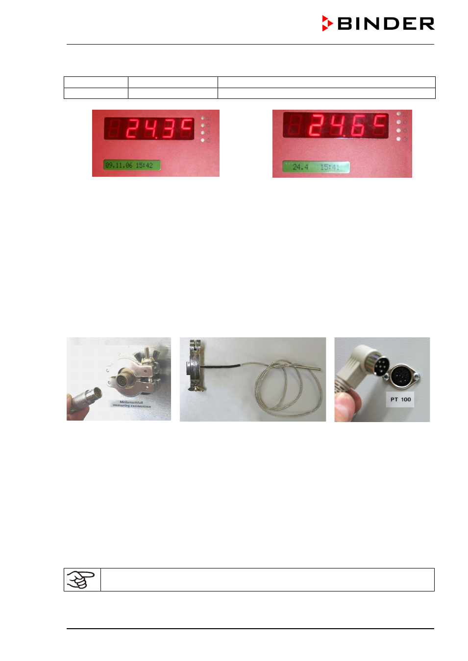
The object temperature is indicated on Display 2 of the RD3 controller.
Display 1 shows
e.g. 24.6
C
(actual temperature value)
Display 2 shows
24.4 15:41
(actual object temperature in °C, actual time)
Figure 23:
Standard Display without the
object temperature display option
Figure 24:
Display with the
object temperature display option
The object temperature data is put out combined with the temperature data of the controller to the RS 422
interface as a second measuring channel. This permits recording by the BINDER documentation software
APT-COM™ DataControlSystem (option, chap. 15.6).
Assembly and connection of the object temperature recording
•
Insert the Pt 100 temperature sensor from the rear through the measuring connection (15) into the
inner chamber.
•
The 3 contacts of the Pt 100 sensor are conducted outside via a measuring access port. From there,
establish the connection to the DIN socket (14) at the top of the rear panel of the unit marked “Pt100”.
For reasons of explosion protection, this electrical connection to the inner chamber is conducted via a
triple internal safety barrier with a conducting-state voltage of 1.6 Volt maximum against ground.
Figure 25:
Figure 26:
Figure 27:
Measuring connection (15)
with measuring access port
Plug for connection cable to
DIN socket “Pt 100”
Measuring current port with universal
eccentric ring and locking ring DN 16, with
flexible Pt 100 temperature sensor
Pt100 connection (14) at
the rear of the unit
Technical data of the Pt 100 sensor:
•
Three-wire technique
•
Class B (EN 60751)
•
Temperature range up to 300 °C / 572°F
•
Stainless steel protective tube, length 45 mm / 1.77 in, stainless steel material no. 1.4501
If the oven is charged to full capacity, depending on the load, deviations from the specified
heating up times may occur.