4 connections at the rear of the unit – BINDER VD 23 User Manual
Page 27
VDL (E2.1) 04/2014
page 27/107
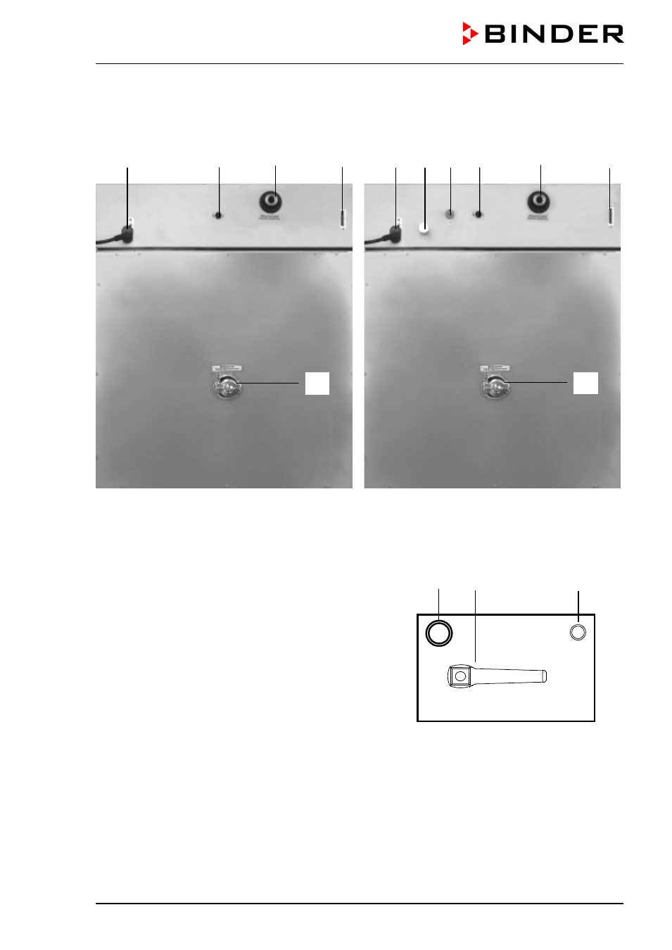
2.4 Connections at the rear of the unit
(10)
(14)
(13)
(9)
VDL 23
(10) (11) (12) (14)
(13)
(9)
VDL 53 / VDL 115
Figure 7: Rear of VDL
(8) Vacuum shut-off valve
(9)
RS 422 serial interface for computer communication
(10) Power connection line
(11) Inert gas connection, adapter with hose olive
∅
8 mm / 0.31 in
(12) Fresh air connection (tube 8x1 mm)
(13) Vacuum connection with small flange DN16
(14) DIN socket “Object-Pt100“ (option) to connect a Pt 100
sensor (with option “object temperature display”)
(15) Measuring connection with small flange DN16
(11)
(8)
(12)
VAC.OFF
VAC.ON
GAS
AIR
Figure 8: Connections left side VDL 23
(15)
(15)