Setup elements, Setup elements –17, Board settings dip switch –17 – Altera Cyclone III LS FPGA Development Board User Manual
Page 25
Chapter 2: Board Components
2–17
Configuration, Status, and Setup Elements
© October 2009 Altera Corporation
Cyclone III LS FPGA Development Board Reference Manual
lists the board-specific LEDs component references and manufacturing
information.
Setup Elements
The development board includes several different kinds of setup elements. This
section describes the following setup elements:
■
Board settings DIP switch
■
JTAG chain header switch
■
Configuration push-button switches
Board Settings DIP Switch
The board settings DIP switch (SW2) controls various features specific to the board
and the MAX
II CPLD EPM2210 System Controller logic design.
shows the
switch controls and descriptions.
D29, D30, D31
PROGRAM
(PGM_LED[2:0])
Green LEDs. Illuminates to show the LED sequence that determines which flash
memory image loads to the FPGA when PGM select push-button switch is
pressed. Driven by the MAX II CPLD EPM2210 System Controller.
D22
ENET TX
Green LED. Illuminates to indicate Ethernet PHY transmit activity. Driven by the
Marvell 88E1111 PHY.
D18
ENET RX
Green LED. Illuminates to indicate Ethernet PHY receive activity. Driven by the
Marvell 88E1111 PHY.
D20
10
Green LED. Illuminates to indicate Ethernet linked at 10 Mbps connection speed.
Driven by the Marvell 88E1111 PHY.
D16
100
Green LED. Illuminates to indicate Ethernet linked at 100 Mbps connection speed.
Driven by the Marvell 88E1111 PHY.
D15
1000
Green LED. Illuminates to indicate Ethernet linked at 1000 Mbps connection
speed. Driven by the Marvell 88E1111 PHY.
D2
HSMA PRSNTn
Green LED. Illuminates when HSMC port A has a board or cable plugged-in such
that pin 160 becomes grounded. Driven by the add-in card.
D1
HSMB PRSNTn
Green LED. Illuminates when HSMC port B has a board or cable plugged-in such
that pin 160 becomes grounded. Driven by the add-in card.
D4
USB
Green LED. Illuminates when the embedded USB-Blaster is in use to program the
FPGA. Driven by the MAX II CPLD EPM2210 System Controller and MAX IIZ.
Table 2–9. Board-Specific LEDs (Part 2 of 2)
Board Reference
LED Name
Description
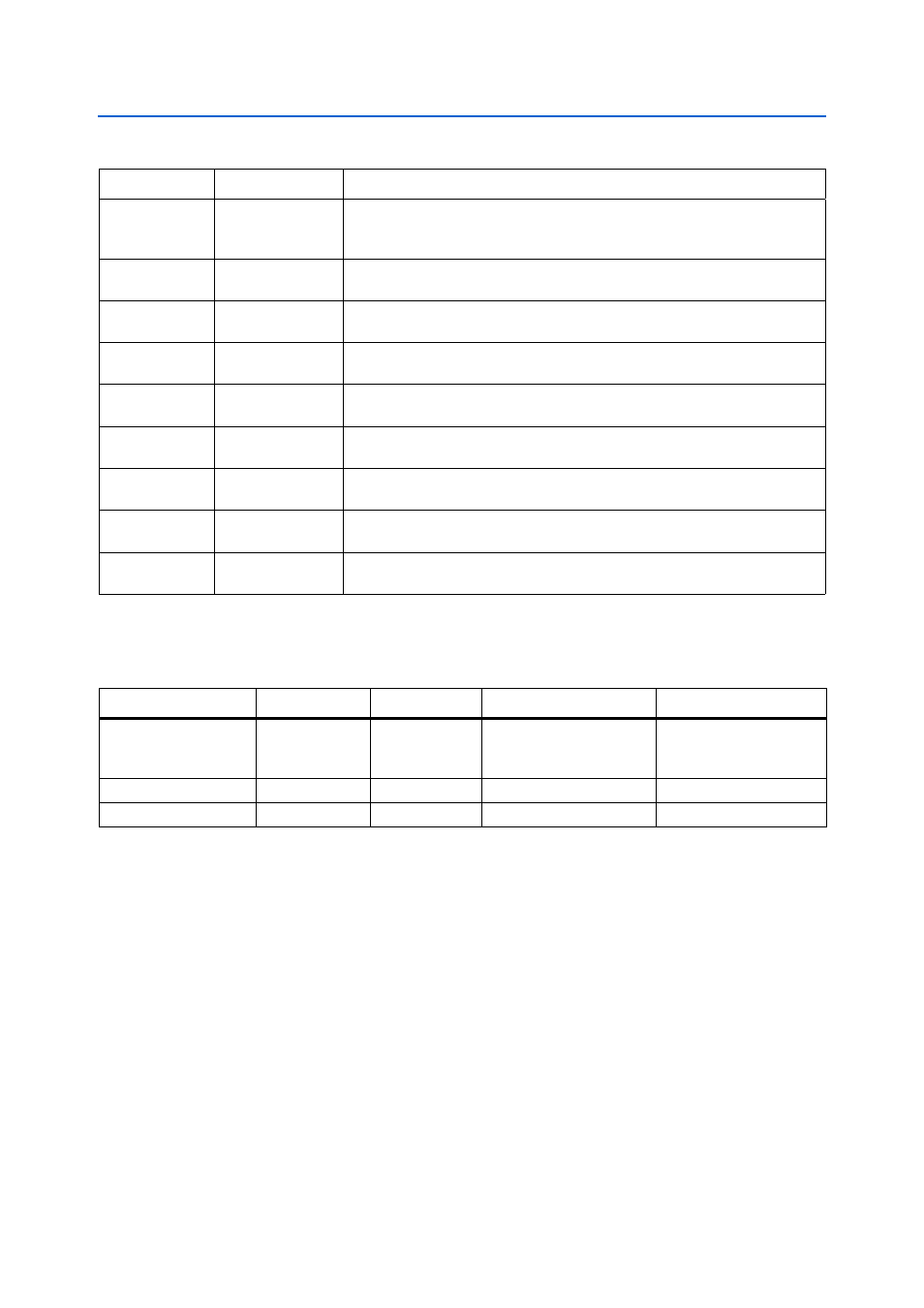
Table 2–10. Board-Specific LEDs Component References and Manufacturing Information
Board Reference
Description
Manufacturer
Manufacturer Part Number
Manufacturer Website
D1, D2, D4, D7,
D11-D16, D18, D20,
D22, D29-D31
Green LEDs
Lumex, Inc.
SML-LX1206GC-TR
D10
Red LED
Lumex, Inc.
SML-LX1206IC-TR
D3
Blue LED
Lumex, Inc.
SML-LX1206USBC-TR