Embedded multipliers operational modes, Bit multipliers, Embedded multipliers operational modes -3 – Altera MAX 10 Embedded Multipliers User Manual
Page 7: Bit multipliers -3
• Clock
• Clock enable
• Asynchronous clear
All input and output registers in a single embedded multiplier are fed by the same clock, clock enable, and
asynchronous clear signals.
Embedded Multipliers Operational Modes
You can use an embedded multiplier block in one of two operational modes, depending on the applica‐
tion needs:
• One 18-bit x 18-bit multiplier
• Up to two 9-bit x 9-bit independent multipliers
You can also use embedded multipliers of the MAX
®
10 devices to implement multiplier adder and
multiplier accumulator functions. The multiplier portion of the function is implemented using embedded
multipliers. The adder or accumulator function is implemented in logic elements (LEs).
18-Bit Multipliers
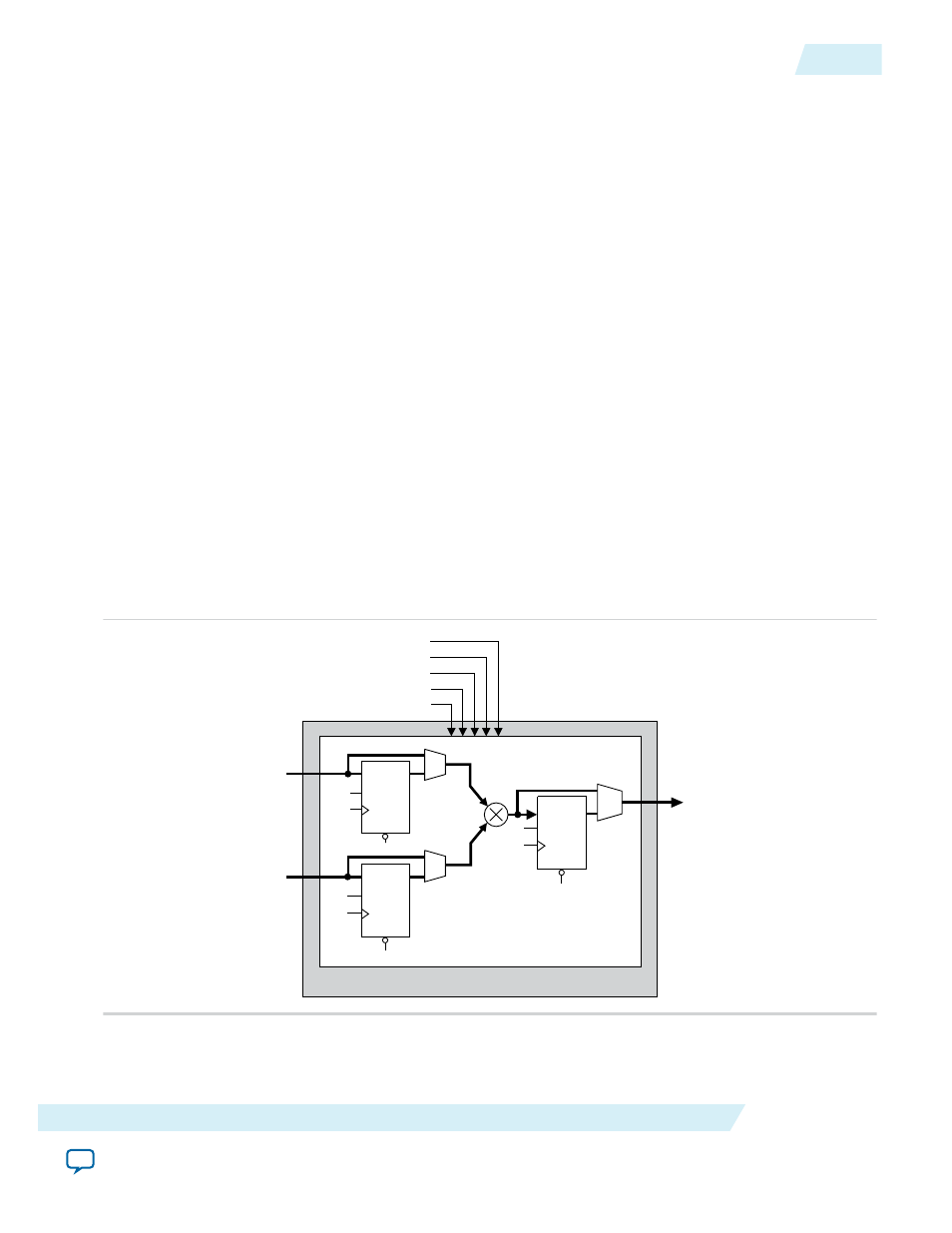
You can configure each embedded multiplier to support a single 18 x 18 multiplier for input widths of 10
to 18 bits.
The following figure shows the embedded multiplier configured to support an 18-bit multiplier.
Figure 2-2: 18-Bit Multiplier Mode
CLRN
D
Q
ENA
Data A [17..0]
Data B [17..0]
aclr
clock
ena
signa
signb
CLRN
D
Q
ENA
CLRN
D
Q
ENA
Data Out [35..0]
18 x 18 Multiplier
Embedded Multiplier
UG-M10DSP
2014.09.22
Embedded Multipliers Operational Modes
2-3
Embedded Multipliers Features and Architecture
Altera Corporation