6 wiring, 1 general wiring guidelines, 2 interface configuration – Pilz PSSu K F INC User Manual
Page 25: Section 6, Wiring, General wiring guidelines, Interface configuration, 6wiring
Wiring
Operating Manual PSSu K F INC
1001688EN06
25
6
Wiring
6.1
General wiring guidelines
Please note:
}
The module's connections are galvanically isolated from the module supply and peri
phery supply.
}
For EMC reasons we recommend that you operate inputs A, B, C exclusively as differ
ential inputs with inverted signals (A+/A, B+/B, C+/C).
}
The module evaluates open differential inputs (A+/A, B+/B, C+/C) as a 1 signal.
}
The module evaluates open function inputs (G, L, S) as a 0 signal.
}
Use twisted pair cables to carry the inverted signals. This will increase the noise im
munity.
}
Use shielded signal cables with metallic plugs. The screening should be connected to
the housing of the DSub connector.
}
The channel for the incremental encoder's zero pulse has a different designation de
pending on the manufacturer (N, C, Z, 0,...)
}
The supply voltages must be extra low voltages with protective electrical separation
(PELV or SELV) in accordance with VDE 0100, Part 410.
}
Use copper wiring.
}
Connect the two sensors via separate cables. This also applies to compact encoders.
6.2
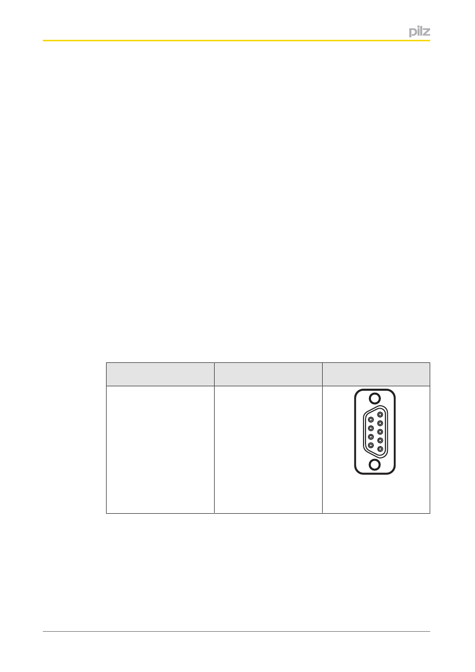
Interface configuration
Connection encoder sig
nals
Layout
Female 9pin DSub con
nector
X1
1: C+
2: B+
3: A+
4: n. c.
5: 0 V counter
6: C
7: B
8: A
9: U
p
(+5 V for sensor)
1
5
9
6