3 transfer counter status via zero pulse, Transfer counter status via zero pulse – Pilz PSSu K F INC User Manual
Page 17
Function description
Operating Manual PSSu K F INC
1001688EN06
17
Key to timing diagram:
Section
Function
Procedure for PSSu in system environ
ment B
a
Activate latch function
In the user program, set Out
putData.LatchOrMeasure
b
Fill latch memory
Rising edge at input L: Counter status is
transferred to the latch memory
c
Output counter status
Set status bit
Counter status is written in In
putData.LatchOrPeriod
The module sets InputData.LatchOrMeas
ureDone
d
Finish latch function
In the user program, reset Out
putData.LatchOrMeasure
e
Ready for new latch func
tion
The module resets InputData.LatchOrMeas
ureDone
The contents of the latch memory remains in the process image of inputs until the module
signals a new memory value by setting the status information. Before the initial transfer the
process image of inputs contains 0000 0000
H
or FFFF FFFF
H.
The module always transmits the counter status when the first latch pulse occurs after the
function has started. All subsequent latch pulses are ignored until the function is completed
and reset.
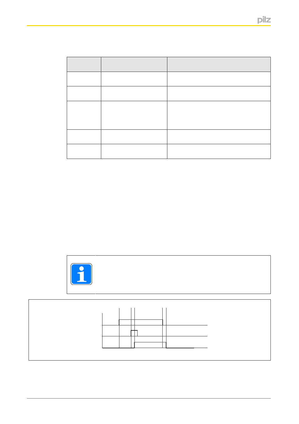
4.1.5.3
Transfer counter status via zero pulse
The output for the incremental encoder's zero pulse is connected to input C (C+/C). An in
cremental encoder typically supplies one zero pulse per rotation. Using the zero pulse func
tion it is possible to record the last counter status before the zero pulse and transmit it via
the process image of inputs.
INFORMATION
In "Counter" operating mode, a rising edge at input C stops the counter.
a
b
PIO
C
PII
c
d e
Legend:
}
PIO: I/O datum OutputData.ZeroPulseActive
}
C: Input C