6 wiring, 1 general wiring guidelines, 1 mechanical connection of the base modules – Pilz PSSu E F ABS SSI User Manual
Page 21: Section 6, Wiring, General wiring guidelines, Mechanical connection of the base modules, 6wiring, Din 5264-a
Wiring
Operating Manual PSSu E F ABS SSI(T)
1001455EN06
21
6
Wiring
6.1
General wiring guidelines
Please note:
}
Use twisted pair cables to carry the differential signals (D+/D and Cl+/Cl). This will in
crease the noise immunity.
}
Use shielded signal cables with metallic plugs.
}
On base modules with Crail:
–
Connect the shield to the terminals on the Crail.
–
Connect the Crail with low impedance to the functional earth.
}
On base modules without Crail:
–
Connect the shield as shown in the terminal configuration section.
The module connects the shield to the mounting rail.
–
Connect the mounting rail to the functional earth via an earthing terminal.
}
The supply voltages must be extra low voltages with protective electrical separation
(PELV or SELV) in accordance with VDE 0100, Part 410.
}
Use copper wiring.
}
Connect the two sensors via separate cables. This also applies to compact encoders.
}
The terminal configuration as stated on the front plate applies for base modules with C
rail. The terminal configuration as stated in the technical documentation applies for all
other base modules.
6.1.1
Mechanical connection of the base modules
Procedure:
}
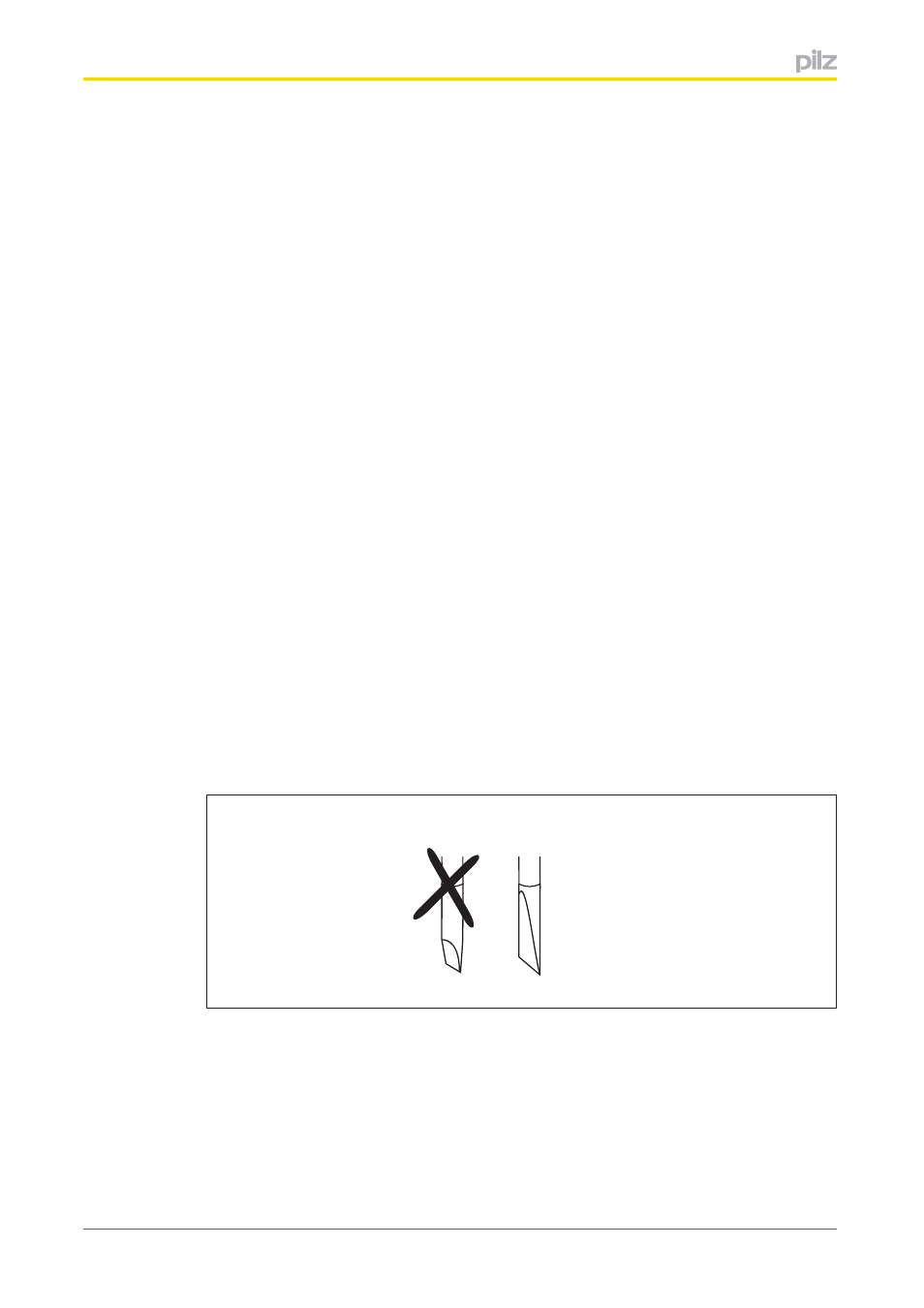
Use a flat blade screwdriver (DIN 5264A)!
DIN 5264-A
}
Strip the wire back 8 mm.
}
If necessary, label the connection level with a colour marker [3].
}
Base module with screw terminals:
–
Use a screwdriver to loosen the screw on the screw terminal [1]
–
Insert the stripped cable into the round fixing hole [2], as far as it will go.
–
Tighten up the screw on the screw terminal.