4 function description, 1 module features, 1 function description – Pilz PSSu E F ABS SSI User Manual
Page 13: Section 4, Function description, Module features, 4function description
Function description
Operating Manual PSSu E F ABS SSI(T)
1001455EN06
13
4
Function description
4.1
Module features
4.1.1
Function description
Module supply
}
The module supply provides the module with voltage.
Periphery supply
}
The supply for the test pulse output is generated from the periphery supply. It is galvan
ically isolated from the periphery supply.
As part of each cycle the module sends a pulse sequence at the test pulse output (Cl) to
the SSI absolute encoder. In turn the encoder transmits its position data. The position data
is read in at the module's input (D) (see timing diagram: SSI data transfer).
With the system software the user can set the following values to adapt the module to the
encoder or higher level control system:
}
Transmission rate
The frequency of the pulses at the test pulse output (Cl) determines the transmission
rate. The user can adapt the frequency to the encoder in a range from 62.5 kHz up to
1.5 MHz (see Technical Details).
}
Input data length:
The module's input data length must be adjusted to the data length of the absolute en
coder.
The module can process up to 32 Bits. The default is 24 Bits.
}
Data format:
The data format in which the module transmits the position data of the connected abso
lute encoder to the head module.
}
Gray code (default)
–
Binary code
The position data is transmitted to the head module via the ST module bus with 4 Bytes, ir
respective of the configured input data length. The module sends additional status informa
tion.
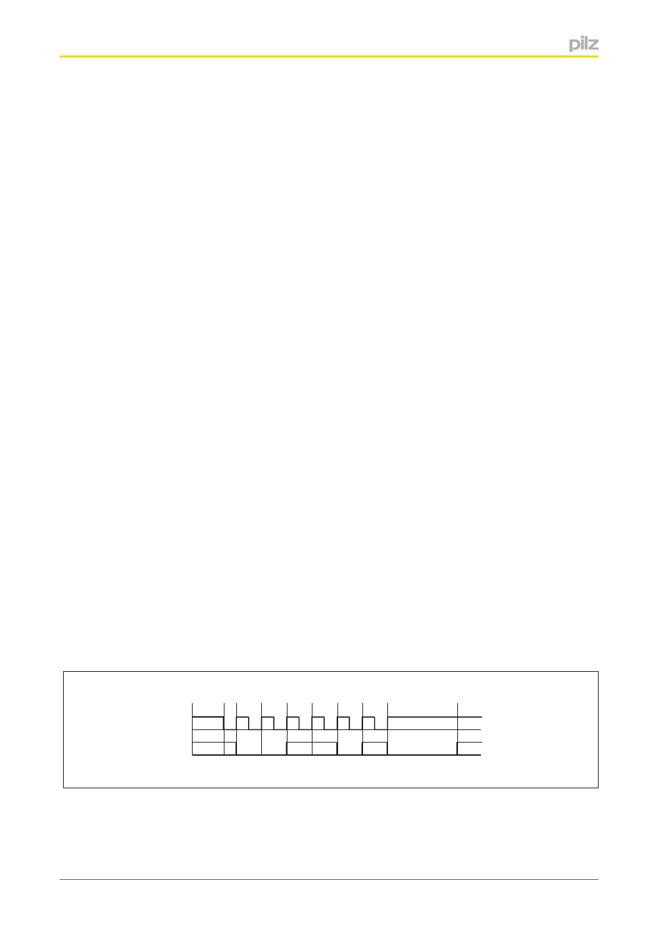
Timing diagram: Example of SSI data transfer:
Cl
D
a
b
d
e
c
Legend:
The bit width in the example is 6. The position of the encoder is 001101 in gray code, i.e. 9
D
.
}
a: Data transfer begins with a falling edge at the Cl signal.