Anwendung, Application – Pilz PNOZ p1p 24VDC 2so User Manual
Page 5
- 5 -
- Manueller Start mit Überwachung:
Taster zwischen S12-S34, Y1-S37
brücken.
Bei Betätigen des Starttasters leuchtet
die LED "START". Erst nach Loslassen
des Starttasters ist das Gerät betriebs-
bereit. Die LED "START" leuchtet nicht
mehr.
• Rückführkreis:
Brücke an Y1-Y2 oder externe Schütze
anschließen.
• 24 V Versorgungsspannung für Halbleiter-
ausgänge: +24 V DC an Klemme Y31 und
0 V an Klemme Y30 anschließen.
Ist das Ausgangssignal für die Ansteuerung
der Erweiterungsgeräte auf dem
PNOZpower-Bus aktiv, dann leuchten die
Statusanzeigen "CH.1 IN", "CH.2 IN" und
"OUT". Das Gerät ist betriebsbereit.
Wird der Eingangskreis geöffnet, dann ist
das Ausgangssignal auf dem PNOZpower-
Bus nicht aktiv. Die Statusanzeige "OUT"
erlischt.
Wieder aktivieren
• Eingangskreis schließen.
• Bei manuellem Start ohne Überwachung
zusätzlich Taster zwischen S33 und S34
betätigen, bei manuellem Start mit
Überwachung Taster betätigen und wieder
loslassen.
Die Statusanzeigen leuchten wieder, die
Sicherheitskontakte sind geschlossen.
Anwendung
In Fig.
3 ... Fig. 9
sind Anschlussbeispiele für
Not-Halt-Beschaltung mit manuellem und
überwachtem Start sowie Schutztüran-
steuerungen.
- Manual reset with monitoring: Connect
button to S12-S34, bridge Y1-S37.
When the starter button is pressed, the
“START” LED will illuminate. The unit is
only ready for operation when the starter
button is released. The “START” LED is
no longer illuminated.
• Feedback control loop:
Bridge Y1 - Y2 or connect external N/C
contacts in series from other devices.
• 24 VDC supply voltage for semi-conductor
output: Connect +24 VDC to terminals Y31
and 0 VDC to Y30.
If the expander unit output control signal is
active on the PNOZpower bus, then the
“CH.1 IN”, “CH.2 IN” and “OUT” status
displays will illuminate. The unit is ready for
operation.
If the input is open circuit, then the output
signal is not active on the PNOZpower bus.
The “OUT” status display will go out.
Reactivate
• Close the input circuit.
• For manual reset without monitoring,
momentary closure of the button between
S33 and S34 must be pressed; for manual
reset with monitoring, press the button and
release again.
The status indicators light up again, the
safety contacts are closed.
Use
In Fig.
3 ... Fig. 9,
there are example
connections for E-STOP wiring with manual
and monitored starts, as well as safety gate
controls.
- Réarmement manuel: câblage d’un
poussoir sur S12-S34
- Surveillance du circuit de réarmement:
câblage d'un poussoir sur S12-S34 et
pontage des bornes Y1-S37.
Lors de l’actionnement du poussoir de
réarmement, la LED “START” s’allume.
Ce n’est qu’après relâchement du
poussoir de réarmement que l’appareil
est prêt à fonctionner. La LED “START”
est alors éteinte.
• Boucle de retour: Pontage de Y1-Y2 ou
branchement des contacts externes
• Alimentation en 24 VCC des sorties
statiques : relier le +24 V DC à la borne
Y31 et le 0 V à la borne Y30.
Si le signal de sortie pour la commande des
modules d’extension sur le bus PNOZpower
est actif, les LEDs de visualisation “CH.1 IN”,
“CH.2 IN” et “OUT” sont allumées. L’appareil
est prêt à fonctionner.
Si le circuit d’entrée est ouvert, le signal de
sortie sur le bus PNOZpower n’est pas actif.
La LED de visualisation “OUT” s’éteint.
Réactivation
• Fermer le circuit d’entrée.
• En cas de réarmement manuel sans
surveillance, appuyer sur le poussoir de
validation entre S33-S34. En cas de
surveillance du circuit de réarmement,
appuyer puis relacher le poussoir de
validation.
Les affichages d'état s'allument à nouveau.
Les contacts de sécurité sont fermées.
Application
Les figures 3 à 9 représentent des exemples
de raccordement pour câblage d’ARRÊT
D’URGENCE avec réarmement manuel auto-
contrôlé et commandes de protecteurs
mobiles.
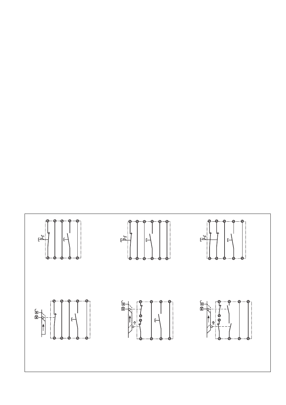
Fig. 5: Eingangskreis zweikanalig, manueller
Start, Querschlusserkennung/Two-channel
input circuit, manual reset, detection of
shorts across the input contacts/Commande
par 2 canaux, validation manuelle, détection
des courts-circuit
Fig. 4: Eingangskreis einkanalig, überwach-
ter Starttaster/Single-channel input circuit,
monitored reset/Commande par 1 canal,
surveillance du poussoir de validation
Fig. 3: Eingangskreis einkanalig, manueller
Start/Single-channel input circuit, manual
reset/Commande par 1 canal, validation
manuelle
Fig. 6: Schutztürsteuerung einkanalig,
manueller Start/Single-channel safety gate
control, manual reset/Surveillance de
protecteur, commande par 1 canal, validation
manuelle
Fig. 7: Schutztürsteuerung zweikanalig,
manueller Start/Two-channel safety gate
control, manual reset/Surveillance de
protecteur, commande par 2 canaux, validation
manuelle
Fig. 8: Schutztürsteuerung zweikanalig,
automatischer Start/Two channel safety gate
control,automatic reset/Surveillance de
protecteur, commande par 2 canaux,
validation automatique
S11 S12
S33
S12
S34
S52
S21
S22
Y1
Y2
S3
S1
S11 S12
S33
S12
S34
S52
S21
S22
Y1
S37
Y1
Y2
S1
S3
S21
S22
S52
S34
S12
S12
S11
S11
Y2
Y1
S1
S3
S52
S34
S33
S12
S11
S22
S12
S21
Y2
Y1
S1
S3
S52
S34
S12
S11
S21
S12
S22
S11
Y2
Y1
S3
S1
S2
S22
S34
S33
S21
S11
S12
S52
S1
S2
S11
Y2
Y1