Montage, Commissioning, Mise en service – Pilz PNOZ p1p 24VDC 2so User Manual
Page 3: Inbetriebnahme, Installation
- 3 -
• Manueller Start mit Überwachung: Gerät
ist erst aktiv, wenn der Starttaster betätigt
und wieder losgelassen wurde.
Montage
• Das Sicherheitsschaltgerät muss in einen
Schaltschrank (min. IP54) eingebaut
werden. Zur Befestigung auf einer
Tragschiene dienen zwei Rastelemente
auf der Rückseite des Geräts.
• Montieren Sie das Gerät auf eine waag-
rechte Tragschiene. Bei anderen Einbau-
lagen können die in den techn. Daten
angegebenen Werte für das Schalt-
vermögen nicht eingehalten werden.
• Das Basisgerät PNOZ p1p kann an
beliebiger Stelle des modularen Sicher-
heitssystems PNOZpower montiert
werden.
• Auf der Geräterückseite des PNOZ p1p
befinden sich 2 Buchsen. Das Basisgerät
PNOZ p1p wird mit den Erweiterungs-
modulen über die mitgelieferten Steck-
brücken verbunden.
Beachten Sie: Auf das erste und letzte
Gerät muss ein Abschlussstecker
gesteckt werden (siehe Fig. 2)!
• Nur Abschlussstecker für das modulare
Sicherheitssystem PNOZpower verwenden
(Aufdruck: Sach-Nr. 95579).
• Maximalbestückung eines PNOZpower-
Systems:
- 1 Basisgerät
- 4 Erweiterungsmodule
- 1 Netzgerät
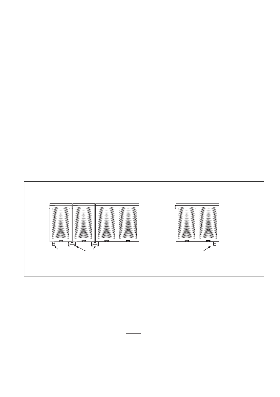
Fig. 2: Montage des PNOZ p1p/Installation PNOZ p1p/Montage du PNOZ p1p
Basisgerät
Base Unit
Appareil
de base
PNOZ p1p
Erweiterungsmodul 1
Expander module 1
Module d'expansion 1
Erweiterungsmodul 4
Expander module 4
Module d'expansion 4
Netzgerät
Power Supply
Bloc
d'alimentation
95579
Abschlussstecker
Terminator
Fiche de
terminaison
95425
Steckbrücke
Link
Cavalier de pontage
95579
Abschlussstecker
Terminator
Fiche de
terminaison
• Manual reset with monitoring: Unit is only
activated, when the reset button ist
pressed and then released.
Commissioning
Please note for operation:
• CAUTION
Only connect and disconnect the plug-in
terminals when no voltage is applied.
• Delivery status: Y1 jumpered to Y2
(feedback loop)
• Calculate the max. cable runs l
max
in the
input circuit:
R
lmax
R
l
/ km
I
max
=
R
lmax
= Max. Total cable resistance
(see technical details)
R
l
/km = cable resistance/km
• Surveillance de circuit de réarmement : le
relais n'est activé qu'après le relâchement
du poussoir de validation.
Mise en service
Remarques préliminaires :
• ATTENTION
Ne branchez et débranchez les borniers de
raccordement débrochables que lorsque
l’alimentation est coupée.
• État à la livraison : pontage entre Y1-Y2
(boucle de retour)
• Calcular les longueurs de câblage max I
max
dans le circuit d’entrée:
R
lmax
R
l
/ km
I
max
=
R
lmax
= résistivité de câblage totale max.
(voir les caractéristiques techniques)
R
l
/km = résistivité de câblage/km
Inbetriebnahme
Beachten Sie bei der Inbetriebnahme:
• ACHTUNG
Die steckbaren Anschlussklemmen nur im
spannungslosen Zustand ziehen und
stecken.
• Auslieferungszustand: Brücke zwischen
Y1-Y2 (Rückführkreis)
• Berechnung der max. Leitungslänge I
max
im
Eingangskreis:
R
lmax
R
l
/ km
I
max
=
R
lmax
= max. Gesamtleitungs-
widerstand (s. technische Daten)
R
l
/km = Leitungswiderstand/km
Installation
• The safety relay must be installed in a
control cabinet (min. IP54). There are two
notches on the back of the unit for DIN rail
attachment.
• Fit the unit to a horizontal DIN rail. In other
mounting positions, the values given in the
technical details for the switching capability
may not be achieved.
• The PNOZ plp base unit can be installed in
any position on the PNOZpower modular
safety system.
• There are 2 sockets on the rear of the
PNOZ p1p. Connect the PNOZ p1p base
unit to the expander modules using the
jumpers supplied.
Please note: Be sure to plug a termina-
tor in to the first and last units
(see Fig. 2)!
• Only use terminators for the PNOZpower
modular safety system (Catalogue: Item
No. 95579).
• Maximum hardware in a PNOZpower
system:
- 1 base unit
- 4 expander modules
- 1 power supply unit
Montage
• Le relais de sécurité doit être monté dans
une armoire avec, au minimum, l’indice de
protection IP54. Sa face arrière, dotée de
2 ergots, peut s’encliqueter sur un profilé
support.
• Montez l’appareil sur un profilé support
horizontal. Les autres positions de
montage ne permettent pas de respecter
les valeurs de commutation indiquées
dans les caractéristiques techniques.
• L’appareil de base PNOZ p1p peut être
installé en n’importe quel point du système
de sécurité modulaire PNOZpower.
• La face arrière du PNOZ p1p comporte 2
douilles. L’appareil de base PNOZ p1p est
relié aux modules d’extension par le biais
des cavaliers de pontage fournis.
Important : le premier et le dernier
appareil doivent être pourvus d’une
fiche de terminaison (voir fig. 2) !
• Utilisez uniquement les fiches de
terminaison prévues pour le système de
sécurité modulaire PNOZpower
(Référence : 95579).
• Équipement maximal d’un système
PNOZpower :
- 1 appareil de base
- 4 modules d’extension
- 1 bloc d’alimentation