Pilz PU3Z 120-240VAC 3n/o 1n/c 6so User Manual
Page 2
- 2 -
Le relais PU3Z répond aux exigences
suivantes :
• conception redondante avec auto-
surveillance
• sécurité garantie même en cas de
défaillance d’un composant
• fusible électronique
• The safety function remains effective in
the case of a component failure.
• The relay has an electronic fuse.
13
L1*
L2
L3*
L1
L3
L2*
S33 S34
Y1 Y2
Y4 Y5
23 33
41
Y41
Y42
Y43
Y44
Y45
Y46
14 24 34
42
N
N*
FAULT
X-Y
X-Y
X-Y
A1
A2
VCC
Xn>Y
Xn>Y
Comparator
galvanic.
Isolation
wire break
monitor
K2
K1
fail safe
block
&
~
=
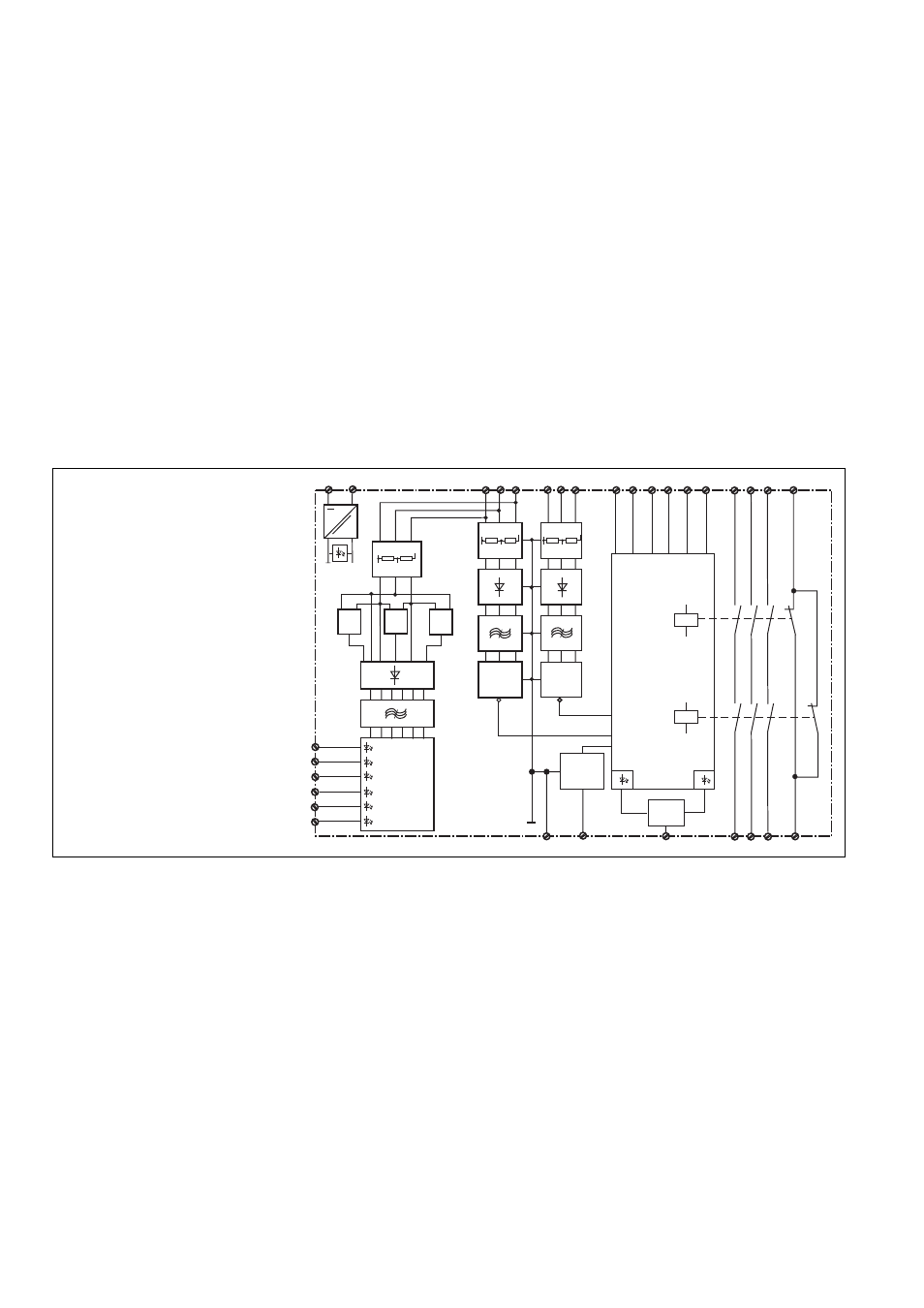
Fig. 1: Schematisches Schaltbild/Wiring
diagram/Schéma interne
Das Schaltgerät erfüllt folgende Sicherheits-
anforderungen:
• Schaltung ist redundant mit Selbstüber-
wachung aufgebaut.
• Die Sicherheitseinrichtung bleibt auch bei
Ausfall eines Bauteils wirksam.
• Das Gerät hat eine elektronische
Sicherung.
Funktionsbeschreibung
Das Spannungsüberwachungsgerät PU3Z
arbeitet als Schwellwertschalter. Die Schalt-
schwellen der drei Phasenspannungen L1,
L2, L3 betragen 10 V AC und 110 V AC
bzw. 64 V AC bei einer Messung gegen den
Nullleiter N.
Voraussetzungen:
• Die Versorgungsspannung ist angelegt
und die LED "Power" leuchtet.
• Der Öffnerkontakt des zu überwachenden
Schütz ist am Eingangskreis angeschlos-
sen.
• Die Messspannungen sind am Messkreis
angeschlossen.
Die Ausgangskontakte melden den Zustand
des Eingangskreises:
• Die Sicherheitskontakte 13-14, 23-24 und
33-34 sind offen und der Hilfskontakt 41-
42 ist geschlossen, wenn der Eingangs-
kreis Y4-Y5 geöffnet (Schütz angezogen)
oder eine der Messspannungen größer
als 10 V AC ist.
• Die Sicherheitskontakte 13-14, 23-24 und
33-34 sind geschlossen und der Hilfskon-
takt 41-42 ist offen, wenn der Eingangs-
kreis Y4-Y5 geschlossen (Schütz
abgefallen) ist und alle Messspannungen
< 10 V sind.
Function Description
The voltage monitor PU3Z operates as a
threshold switch. The switching threshold of
the three phase voltages L1, L2, L3 are 10
VAC and 110 VAC/64 VAC when measured
against N.
Requirements:
• The voltage is supplied and the LED
"Power" is illuminated.
• The normally closed contact on the
monitoring contactor is connected to the
input circuit.
• The measured voltages are connected to
the measuring circuit.
The output contacts signal the status of the
input circuit:
• The safety contacts 13-14, 23-24 and 33-
34 are open and the auxiliary contact 41-
42 is closed, if the input circuit Y4-Y5 is
open (relay energised) or one of the
measured voltages >10 VAC.
• The safety contacts 13-14, 23-24 and 33-
34 are closed and the auxiliary contact
41-42 is open, if the input circuit Y4-Y5 is
closed (relay de-energised) and all
measured voltages <10V.
Description du fonctionnement
Le relais de tension PU3Z est un relais à
seuil. Les seuils de déclenchement fixes
es phases L1, L2, L3 sont de 10 V AC et
110 V AC ou 64 V AC en cas de mesure
par rapport au neutre.
Préalable :
• La tension d'alimentation est présente et
la LED "Power" est allumée.
• Le contact à ouverture du contacteur à
surveiller est relié au circuit d'entrée.
• Les tensions à surveiller sont reliées aux
circuits mesure.
Les contacts de sortie informent de l'état du
circuit d'entrée :
• Les contacts de sécurité 13-14, 23-24 et
33-34 sont ouverts et le contact d'info 41-
42 est fermé, si le circuit d'entrée Y4-Y5
est ouvert (contacteur fermé) ou si une
des tensions mesurées est supérieure à
10 VAC.
• Les contacts de sécurité 13-14, 23-24 et
33-34 sont fermés et le contact d'info 41-
42 est ouvert, si le circuit d'entrée Y4-Y5
est fermé (contacteur reombé) et si
toutes les tensions mesurées sont < à 10
VCA.