StorCase Technology InfoStation 12-Bay 4U Ultra160/SATA User Manual
Page 26
InfoStation 12-bay RAID User's Guide - Rev. C00
StorCase Technology, Inc.
RAID Controller Configuration
15
When the Enter button is pressed in Operation Mode, the RAID Controller will go into
Configuration Mode.
NOTE:
Configuration Mode will automatically cancel after 3 minutes (180 seconds) of
User inactivity.
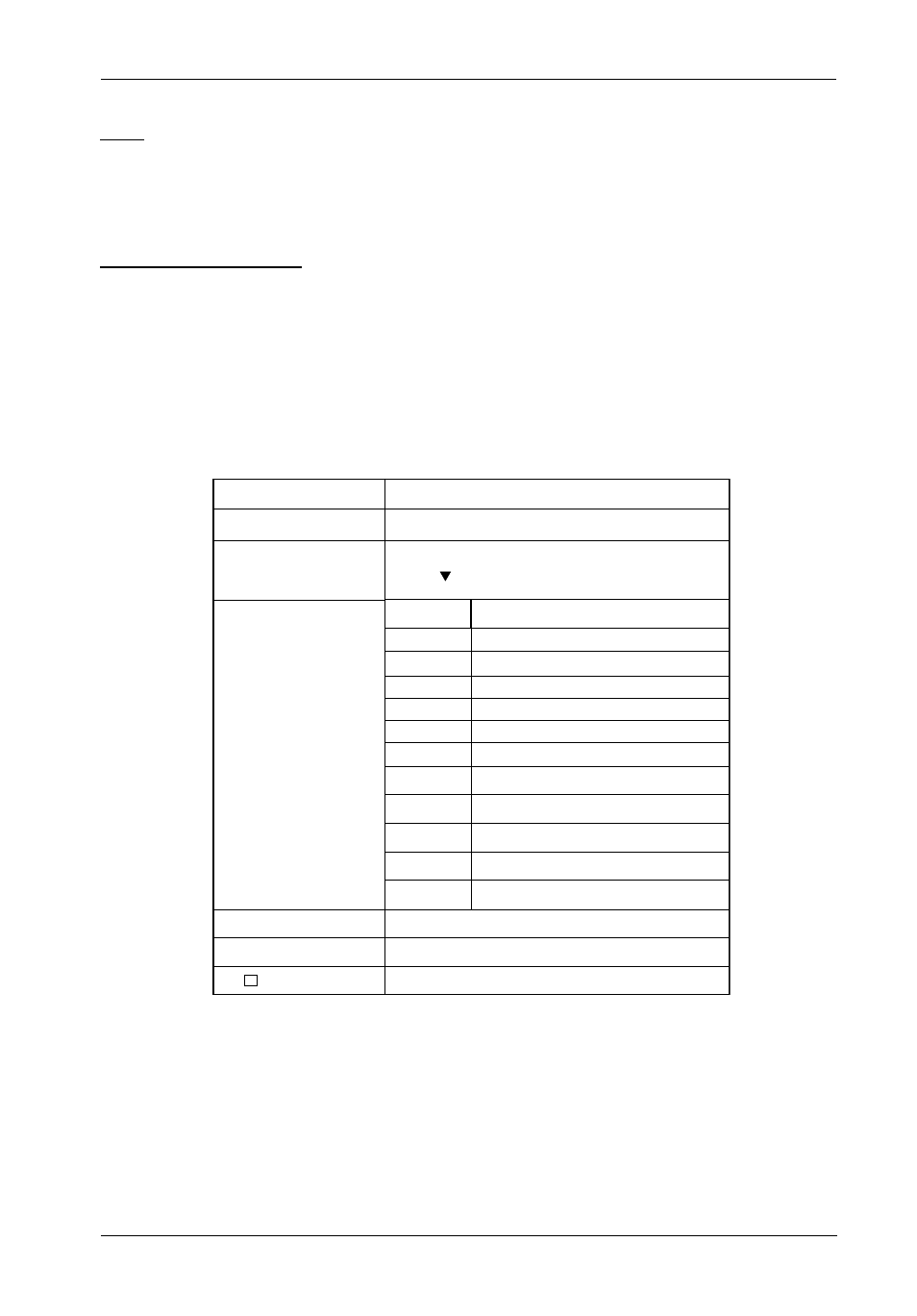
Table 2: LCD Display Components
LEDs
Activity
Indicates data is being accessed
Power
Indicates power is ON
Control Panel Buttons
é
Use to scroll UP through the menu items
ê
Use to scroll DOWN through the menu items
ENT
Use to select a menu item, open a sub-menu, or to select a a value
ESC
Use to exit a sub-menu and return to the previous menu
Field
Description
IFS xxxx/xATA - R
OOOOOOOOOOOS
Symbol
Description
Model number*
Disk status. The farthest O to the left is Disk 1.
Press button to view the next page.
X
A
O
S
R
I
Disk is not installed.
Disk is being added.
Disk is Online (Single Array).
Disk is a spare disk.
Disk is removed.
Disk is being checked.
Rx
ID:x
RAID level (x = 0, 0+1, 1, 3, or 5) configuration.
SCSI ID configuration (x=0-15).
Alternating cursor indicating operational status.
1
2
3
4
J
Array 1 Online (Multiple Array).
Array 2 Online (Multiple Array).
Array 3 Online (Multiple Array).
Array 4 Online (Multiple Array).
JBOD (Just a Bunch of Disks)
*
IFS U160/SATA-R = InfoStation U160-to-Serial ATA enclosure
IFS U160/PATA-R = InfoStation U160-to-Parallel ATA enclosure
IFS FC/SATA-R = InfoStation FC-to-Serial ATA enclosure
IFS FC/PATA-R = InfoStation FC-to-Parallel ATA enclosure