Typical fibre channel configuration – StorCase Technology InfoStation 12-Bay 4U Ultra160/SATA User Manual
Page 23
12
SCSI Channel and FC Configurations
StorCase Technology, Inc.
InfoStation 12-Bay RAID User's Guide - Rev. C00
TYPICAL FIBRE CHANNEL CONFIGURATION
(For FC-to-SATA version only)
CAUTION:
DO NOT bend the LC (optical) cable beyond the cable's minimum bend radius,
data transmission degradation may occur. Follow cable manufacturer's
guidelines for bend radius limitation.
WARNING:
DO NOT look directly into the open end of an active LC (optical) cable or optical
SFP module (with plugs removed)! Serious eye damage can occur from direct
exposure to the infrared light!
NOTES:
The configuration and use of the InfoStation RAID Controller requires a certain
level of expertise and experience on the part of the user/integrator. Since there
are many configuration options and variables (ie. host platforms, applications,
etc.), only general guidelines will be discussed in this User's Guide.
LC (optical) SFP Modules support both 2Gbps and 1Gbps operation.
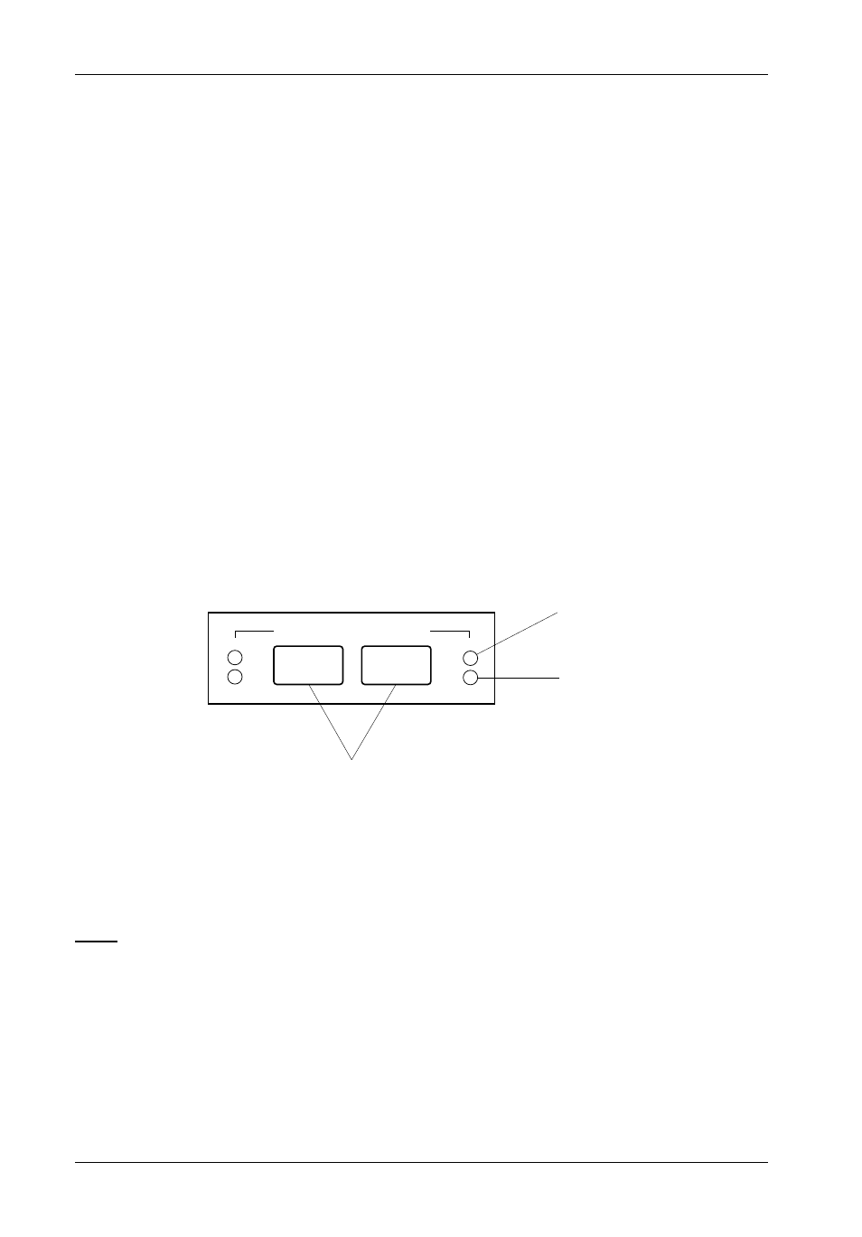
Figure 7A: FC Ports and LEDs
Loop B
Loop A
ST
ACT
ST
ACT
Status LED
Activity LED
FC Ports
LEDs
Status
ON =
Steady glow during power up indicates RAID controller initialization
(will turn OFF once initialization is complete and if SFP is not connec-
ted to Host). LED will remain ON if SFP is connected to Host.
Activity
ON =
Steady glow indicates activity
(Blue)