Front panel – StorCase Technology InfoStation 12-Bay 4U Ultra160/SATA User Manual
Page 16
Introduction
5
InfoStation 12-Bay RAID User's Guide - C00
StorCase Technology, Inc.
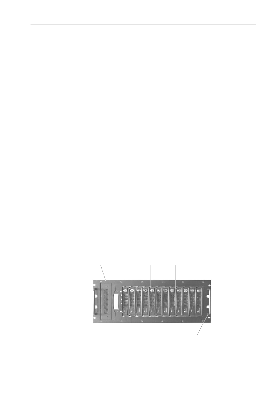
Front Panel
(Figure 2)
5.25" Bay - One bay can accommodate one (1) half-height SCSI device.
RAID Control Panel - Refer to Figure 7.
Drive Carrier(s) - Accommodate up to twelve (12) 3.5" low-profile Parallel ATA or
Serial ATA devices. Backplane design eliminates cable connections to drives,
increases data integrity, and supports drive hot swappability.
Drive Carrier LED(s) - Provides the following information:
Drive Ready (Blue) -
Indicates that the drive is properly installed and ready
for access.
Drive Fault (Red) -
Indicates a drive failure.
Drive Activity (Amber) -
Indicates that the drive is being accessed.
Refer to Figure 5 & Table 1 for further information.
Key Lock(s) - Assure proper seating of the drive carrier within the chassis and
prevent unauthorized removal or installation of the carrier.
NOTE:
The key lock is only to prevent unauthorized removal or installation of the
drive carrier. Locking the key lock is not requried for drive carrier oper-
ation.
Chassis Handle(s) - Provide a sturdy grip for the installation and removal of the
rack-mount chassis.
RAID
Control
Panel
5.25
Bay
Drive Carrier
Handle
Key
Lock
Chassis
Handle
Drive Carrier
LEDs
Figure 2: InfoStation Front Panel