Ntellisys, Daptive, Ressure – Nor-Cal Intellisys Adaptive Pressure Controllers User Manual
Page 5: Ontrollers, 0 - device specification
Call toll free
800-824-4166
or 530-842-4457
•
FAX 530-842-9130
5
I
ntellIsys
A
dAptIve
p
ressure
C
ontrollers
APC-OP-LIT 1/12
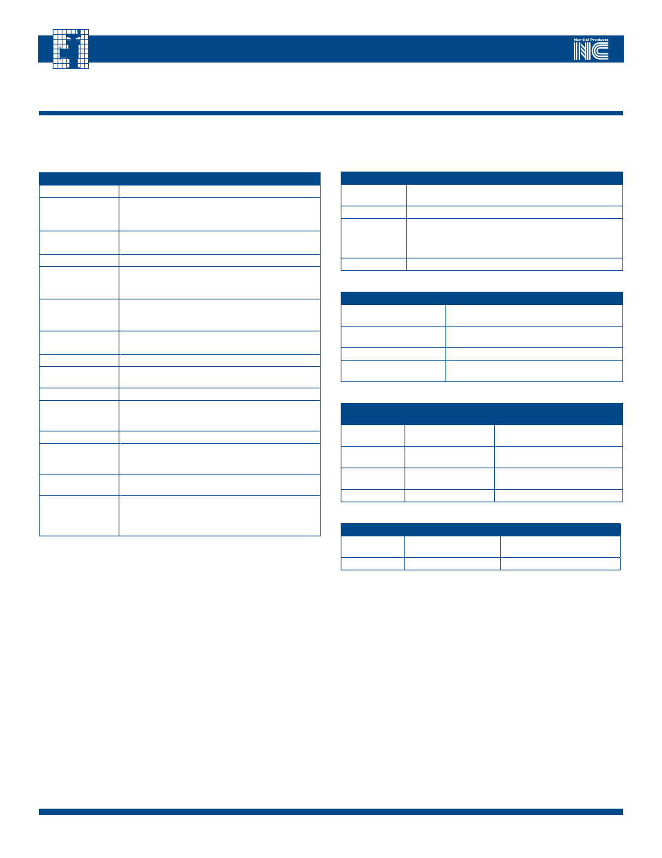
2.0 - Device Specification
The following tables summarize specifications essential to the installation and hook-up of the APC-Series product. Please note that the information herein is lim-
ited to the APC controller. For valve installation instructions and guidelines, please refer to the appropriate Valve Operating Manual.
TAbLE 2.2 – APC CONTROLLER ANALOG TTL I/O
FeAture
SPecIFIcAtIon
Analog (Gauge)
Input
0 to 10V differential
Analog Output
0 to 10V differential @ 35 mA, short circuit protected
TTL Input
Diode protected at –0.4 VDC, compatible with open collector
relay closure or standard logic signals, 25V max. Maximum
low input voltage is 0.6V and minimum sink current is 1 mA.
Minimum high input voltage is 2.5V, or open.
TTL Output
Open collector, optically isolated, 25V @ 10 mA max
TAbLE 2.3 – APC CONTROLLER RS-232 SERIAL I/O
FeAture
SPecIFIcAtIon
Communications Settings
Factory configured at 9600 baud, 1 stop bit,
no parity, 8-bit character
Connections
Rxd Data, Txd data and Common.
No handshake connections.
Communications Protocol
See Section 6.0 in this manual
End of line delimiter
Carriage return (ASCII 0x0D) or Line Feed (ASCII
0x0A) or carriage return then line feed in that order
TAbLE 2.4 – APC CONTROLLER PERFORmANCE
FeAture
ButterFly
vAlveS
GAte & PenDulum vAlveS
Valve speed
(open to closed)
125 to 250 msec,
depending on valve size
2 to 5 sec, depending on valve size
Control range
0.5% to 100% of
gauge
0.5% to 100% of gauge
Accuracy
0.25% of reading 5mV
min
0.25% of reading 5mV min
Repeatability
0.12% of reading
0.12% of reading
TAbLE 2.5 – APC CONTROLLER RELIAbILITy
FeAture
ButterFly vAlveS
PenDulum vAlve
Electronics
MTBF
>10,000 hours
>10,000 hours
Warranty
1 year
1 year
TAbLE 2.1 – APC CONTROLLER GENERAL EqUIPmENT SPECIFICATIONS
FeAture
SPecIFIcAtIon
Dimensions
Please refer to the diagram specific to sections 3.1 to 3.5
Weight, in lbs (kg)
IQA and IQD models: N/A, included in valve weight
Low voltage models: 2.0 (0.9)
A/C powered models: 3.5 (1.6)
Rated Input Voltage
Low voltage models: 24 VDC ±10%, differential
A/C powered models: 100 to 240 VAC
Rated Frequency
A/C Powered models only: 50-60 Hz
Rated Current
Low voltage models: 3.0 A @ 24 VDC max,
1.0A @ 24 VDC average
A/C powered models: 1.0A typ @ 115 VAC 3A max
Rated Input
Protection
Low voltage models: 35 volts max, reverse-
and internal current resettable fuse
A/C powered models: 300 VA slow blow fuse
Rated Output Power
(for gauge excitation)
Low voltage models: ± 15 VDC @ 700 mA
A/C powered models: ± 15 VDC @ 800 mA, 2X
Protection Class
I
Degree of Protection
(IP)
X0
Laser Class
1 (LED’s)
Certifications/EU
Directives
CE Standard for Process Equipment including EMC Directive
89/336/EC for D/C powered models. Low Voltage Directive
2006/95/EC to EN 61010-1:2001 for A/C powered models
Maximum Altitude
6562 ft (2000 m)
Allowable Ambient
Operating
Temperature
32ºF to 113ºF (0ºC to 45ºC)
Allowable Ambient
Humidity
0 to 95% non-condensing
Installation Clearance
3” (75 mm) on all perforated sides. A minimum of 3½”
(90 mm) is needed to allow for connectors. If access and
line of sight is required for LED’s and switches a minimum
of 6” (150mm) is required on those sides.