Ntellisys, Daptive, Ressure – Nor-Cal Intellisys Adaptive Pressure Controllers User Manual
Page 25: Ontrollers
25
Call toll free
800-824-4166
or 530-842-4457
•
FAX 530-842-9130
I
ntellIsys
A
dAptIve
p
ressure
C
ontrollers
APC-OP-LIT 1/12
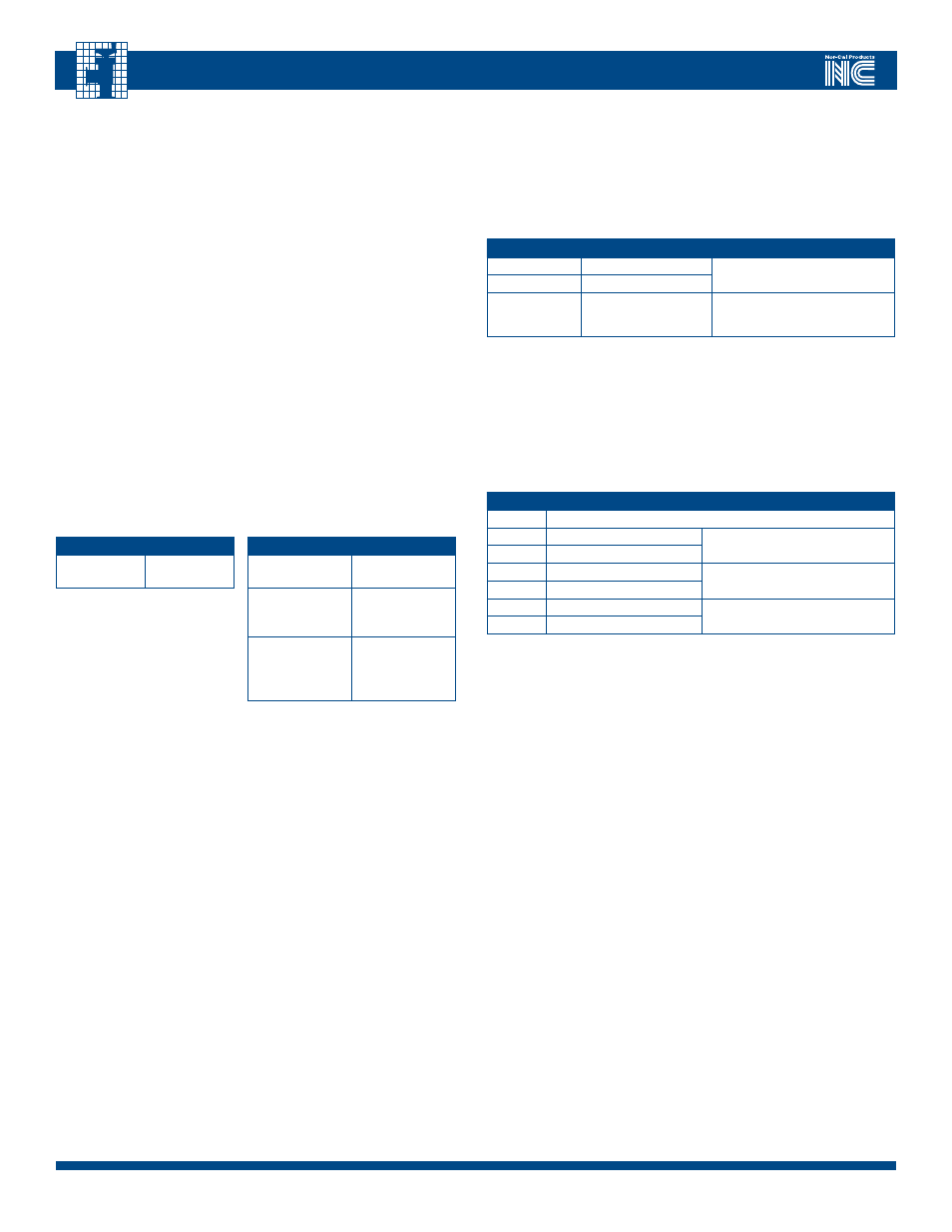
TAbLE 8.5
INPUT ASSEmbLy FORmATS
InStAnce
hex
vArIABleS
2
Exception status
Process variable
4
Exception status
Process variable
Control setpoint
5
(default)
Exception status
Process variable
Control setpoint
Valve position
TAbLE 8.4
OUTPUT ASSEmbLy FORmATS
InStAnce
hex
vArIABleS
7
(default)
Control setpoint
Control instance
how to read system pressure and valve position:
•
Select the service code
0E
(get attribute)
•
Select class ID
31
(select the s-analog sensor object)
•
Select instance ID
1
(process input CDG1)
•
Select attribute ID
6
(value attribute)
•
The device will respond with data bytes 00 00
meaning that the measured pressure is 0
•
Select instance ID
3
(valve position)
•
Select attribute ID
6
(value attribute)The device will respond
with data bytes
FF 7F
meaning that the valve position is full open
Input / Output messaging:
I/ O messaging is used to read and write data to the device on a periodic basis.
They are used for transmission of a continuous stream of data such as setpoint
or process pressure. I/O messages have limited overhead and rely on a prear-
ranged set of data called assemblies. The IQD controller handles input assem-
blies and output assemblies in a poll connection. In an I/O poll connection the
master periodically sends an output assembly and the slave responds with an
input assembly. The IQD Controller supports one output assembly and 3 input
assemblies format.
Example of I/O messaging transactions:
The following is an example format of a typical poll connection:
After having opened the I/O connection the master sends the following data:
Byte
DeScrIPtIon
DAtA rAnGe
1
setpoint (low byte)
0 to 7FFFhex
2
setpoint (high byte)
3
setpoint destination
01 pressure control high gauge
02 valve position control
03 pressure control low gauge
Note:
The setpoint is a number from 0000 to 7FFF covering the range 0 to
100%. In other words, in pressure control mode, 7FFFhex represent full scale
of the primary pressure gauge, if the pressure gauge used is 1 torr then a set
point of 4000hex will control pressure to 0.5 torr.
In valve position control mode, 7FFFhex represents full open stroke.
Respectively, 0000hex setpoint corresponds to closing the valve and 7FFFhex
corresponds to a full open the valve.
The controller response is formatted accordingly:
Byte
DeScrIPtIon
DAtA rAnGe
1
exception status
2
pressure (low byte)
0 to 6000hex
3
pressure (high byte)
4
setpoint (low byte)
0 to 7FFFhex
5
setpoint (high byte)
6
valve position (low byte)
0 to 7FFFhex
7
valve position (high byte)