Tooling configuration, Adding a tool, 11 tooling – LINK Systems LinkNet II User Manual
Page 46: Configuration
4.11 Tooling
Configuration
For LinkNet to track tool
strokes and other tooling
related preventive
maintenance, tooling must be
configured and associated
with jobs. Figure 3.2 shows
the relationship between a
machine, tooling, material, a
job, and a part.
To configure tooling,
select “Configure” and then
“Tooling” from the LinkNet
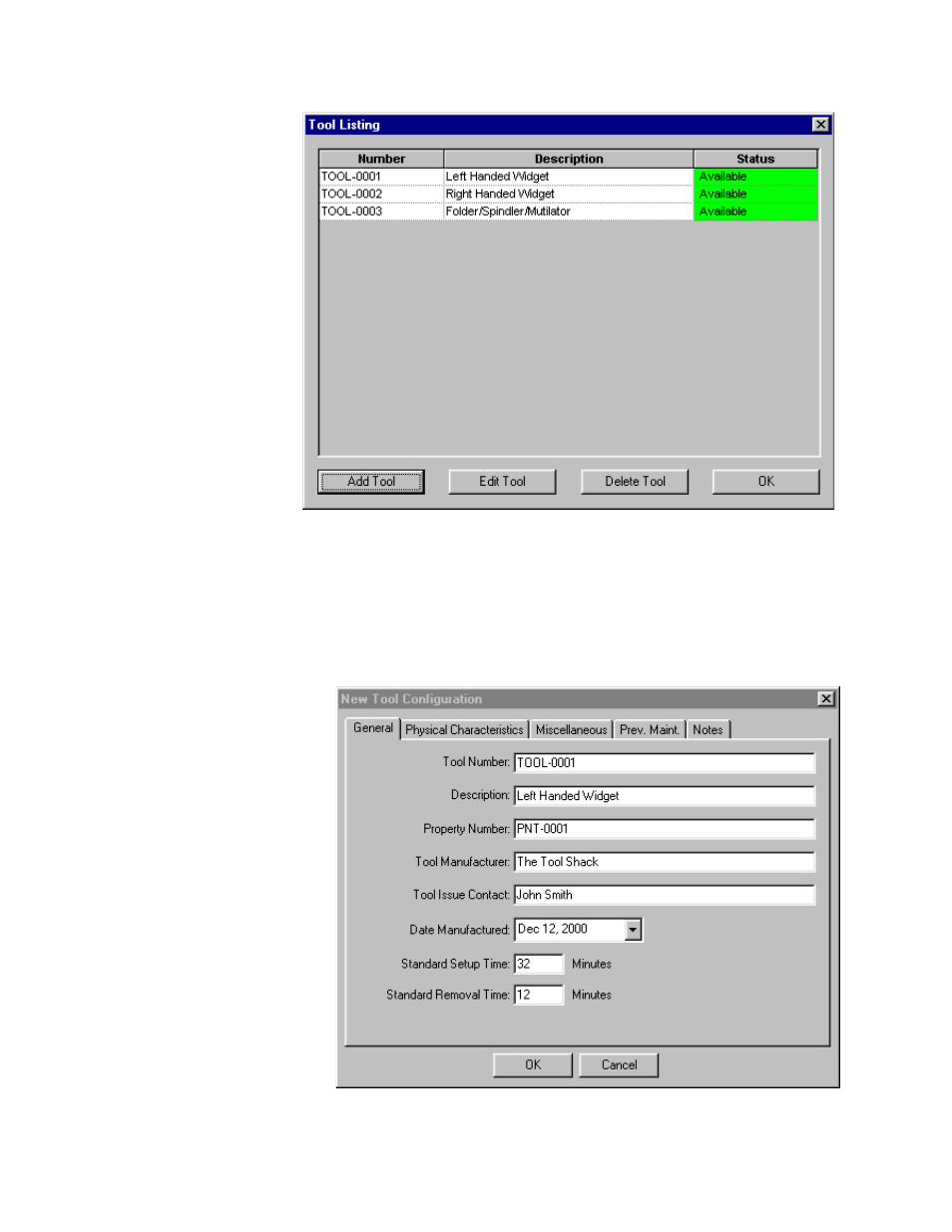
menu. A tool listing similar
to Figure 4.27 will appear.
The listing shows the tool
number, tool description, and
tool status of all currently
configured tools.
The tool status is either
“Available”, “Down For
Scheduled Maintenance” or
“Down For Non-Scheduled Maintenance”. Buttons at the bottom of the list box are also provided to
add, edit, or delete tools.
Figure 4.27: Tool Listing
4.11.1 Adding a Tool
Figure 4.28: Tool Configuration General Settings Dialog Box
To add a tool, hit the “Add
Tool” button at the bottom of the
tool listing as shown in Figure
4.27. A dialog box similar to
Figure 4.28 should appear. Note
that this dialog box has “tabs”
along the top showing “General”,
“Physical Characteristics”,
“Miscellaneous”, “Prev. Maint.”,
and “Notes”. Each of these tabs,
when hit, will bring up a different
page of options for the tool. The
following sections detail each
page of settings.
Manual Version 1.1
10/28/2001
4.24