Figure 2.5, Omnilink ii lcd operator terminal (front view), Figure 2.6 – LINK Systems LinkNet II User Manual
Page 15
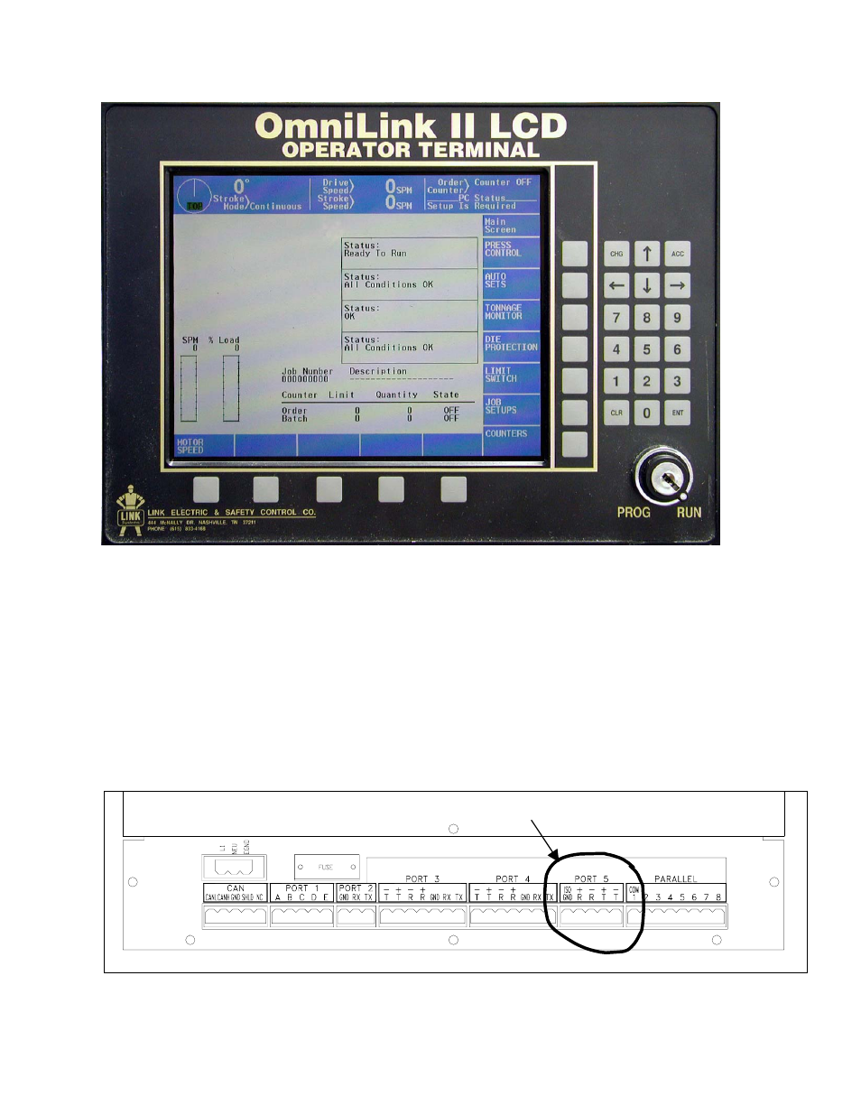
2.4 OmniLink II LCD Operator Terminal Network Connections
Figure 2.5: OmniLink II LCD Operator Terminal (Front View)
There are eight connectors and a fuse on the back panel of the OmniLink II LCD operator terminal
as shown in Figure 2.6. Port 5 is the network port and should be wired as follows:
ISO GND Green/White and White/Green
+R
Orange/White
-R
White/Orange
+T
Blue/White
-T
White/Blue
Network Port
Figure 2.6: OmniLink II LCD Operator Terminal (Back Panel View) Network Connections
Manual Version 1.1
10/28/2001
2.5