Application guide, Plm+ series operation manual rev 1.0.0 – Lab.gruppen PLM 20K44 User Manual
Page 79
10. Application Guide
PLM+ SERIES Operation Manual rev 1.0.0
79
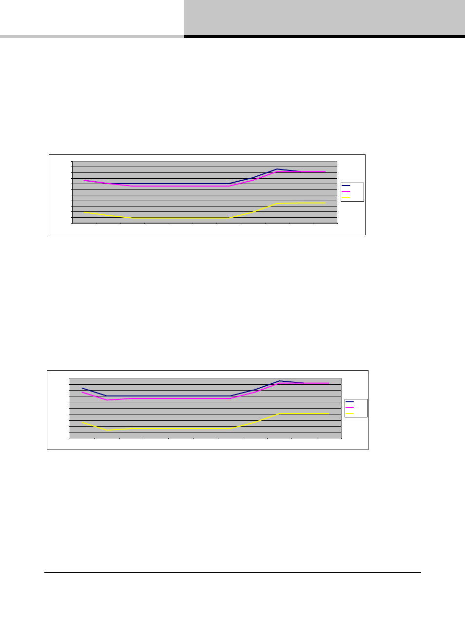
Figure 10.5 illustrates how to minimize absolute noise while achieving full power. In this illustration it can be seen
that there is no available headroom.
• Input Clip: 12 dBu
• Amp Gain: 30.9 dB
• SNR: 111.3 dB
• Absolute Noise Floor: -68.4 dBu
Table 10.5: Analog: Low Noise with Full Output Power (Low Input / High SPL)
Figure 10.6 illustrates how moderate noise with extreme SPL can be achieved. SPL is extremely high in this
example as maximum headroom is available at the input and within the processing stage. This makes it possible to
increase the average SPL by utilizing internal compression capabilities.
• Input Clip: 0 dBFS
• Amp Gain: 35 dB
• SNR: 114.2 dB
• Absolute Noise Floor: -71.3 dBu
-140.0
-120.0
-100.0
-80.0
-60.0
-40.0
-20.0
0.0
20.0
40.0
60.0
Analog
AES Input
Input Mixer
Module In
Module Out
Amp
Attenuation
Analog Ref
Amp Gain
ISVPL
Output
dB
/d
Bu
Clip
Nominal
Noise
Table 10.6: Analog Input: Moderate Noise with Very High Output (Very High SPL)
-140,0
-120,0
-100,0
-80,0
-60,0
-40,0
-20,0
0,0
20,0
40,0
60,0
80,0
Analog
AES Input
Input Mixer
Module In
Module Out
Amp
Attenuation
Analog Ref
Amp Gain
ISVPL
Output
dB
/d
B
u
Clip
Nominal
Noise