Front panel interface, Temperature view – Lab.gruppen PLM 20K44 User Manual
Page 41
7. Front Panel Interface
PLM+ SERIES Operation Manual rev 1.0.0
41
6
LoadPilot Status: 1. High Freq Pilot tone Enabled/Disabled, 2. Low Freq Pilot tone Enabled/Disabled, Status
7
LoadPilot Status: 1. High Freq Pilot tone Enabled/Disabled, 2. Low Freq Pilot tone Enabled/Disabled, Status
8
LoadPilot Status: 1. High Freq Pilot tone Enabled/Disabled, 2. Low Freq Pilot tone Enabled/Disabled, Status
9
Current View title & Frame label, Frame faults and warnings
• The Voltage Meter (V) indicates the power output stage voltage relative to its clip level
• The Current Meter (I) indicates the current the power output stage is driving into its load, relative to the
maximum permissible current the fixed CPL allows
• The Power Meter (P) indicates the instantaneous output power being developed in the load relative to the
PLM+s maximum output power capability.
• The Gain Reduction Meter (L) indicates the degree of limiting being applied by the PLM+ ISVPL and/or the Lake
LimiterMax.
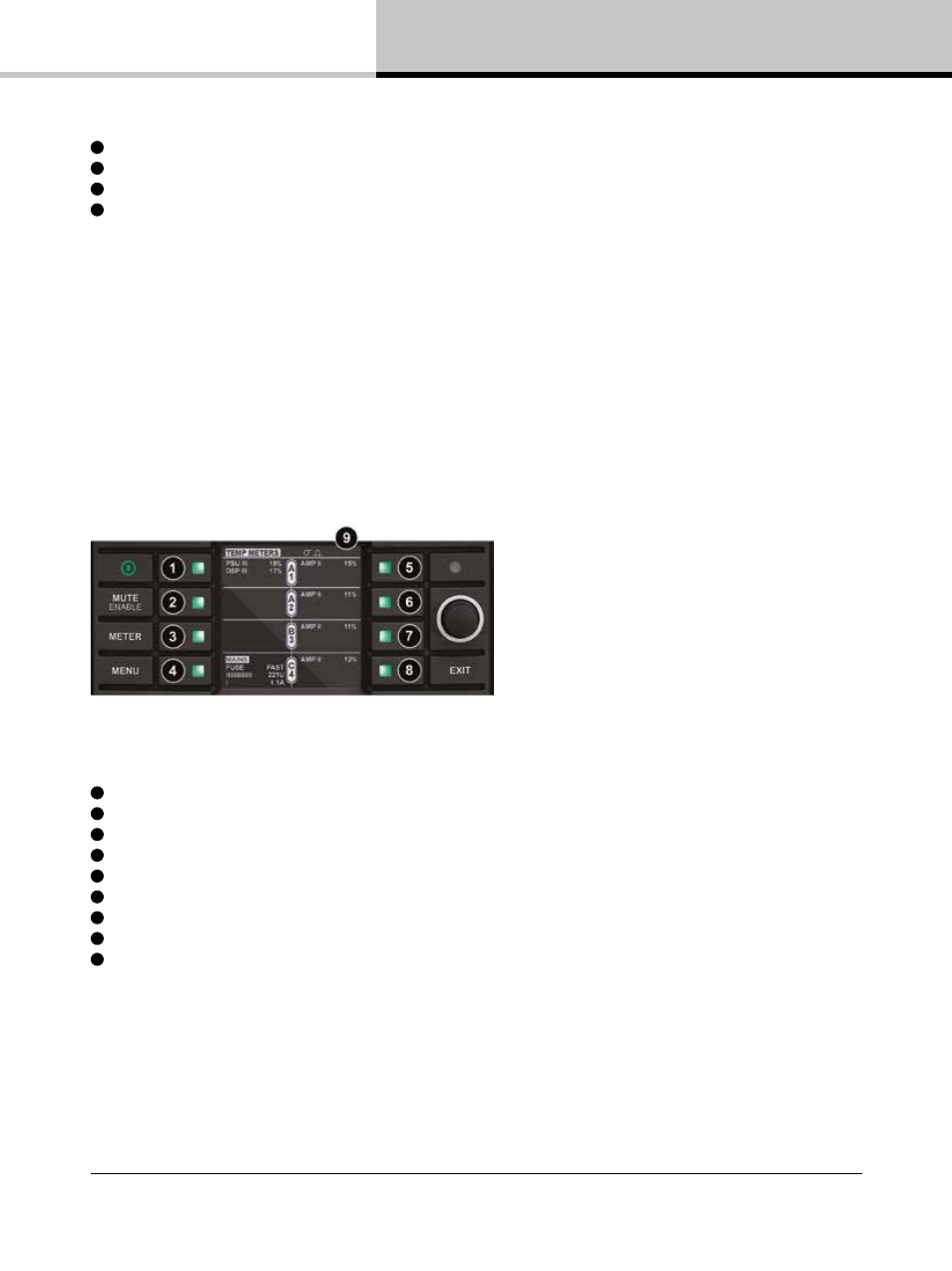
7.10.3. Temperature View
Temperature View provides information about the current operating temperatures within the PLM+. Selected fuse
type, as well as Mains Voltage and Current draw.
Figure 7.10: Meter Mode > Temperature View
1
Current View title. Power supply temp (PSU) & Lake processor temp (DSP) as percentage of maximum
2
Unused in Temperature View
3
Unused in Temperature View
4
Breaker Emulation Limiter; selected Fuse type - Mains Voltage - Mains Current Draw
5
Output 1: AMP - Temp of power output as percentage of maximum
6
Output 2: AMP - Temp of power output as percentage of maximum
7
Output 3: AMP - Temp of power output as percentage of maximum
8
Output 4: AMP - Temp of power output as percentage of maximum
9
Current View title & Frame label, Frame faults and warnings