Front panel interface, Home view – Lab.gruppen PLM 20K44 User Manual
Page 39
7. Front Panel Interface
PLM+ SERIES Operation Manual rev 1.0.0
39
7.10. Meter Mode
7.10.1. Home View
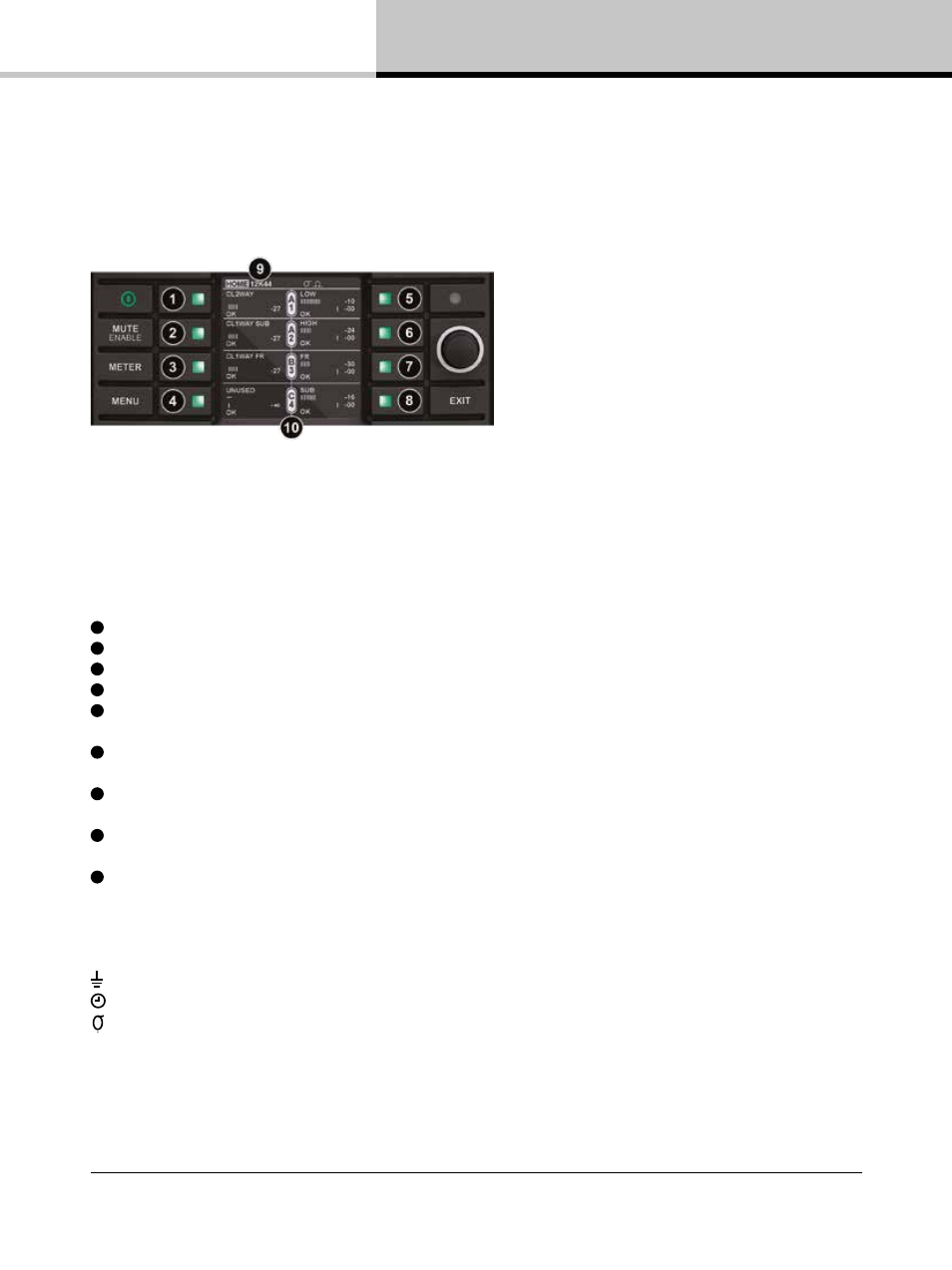
The default view when powering on the device is Meter Mode > Home View as shown in Figure 7.7.
Figure 7.7: Meter Mode > Home View
Home View provides a summary of Module I/O gain level and limiter gain reduction, along with frame, module and
channel labeling information. The example in Figure 7.7 shows a mono 2-way, with Module A feeding power output
channels 1 & 2, and Module B configured as CL1-way feeding a subwoofer on power output channel 3.
Module C is configured for driving a full-range loudspeaker on power output 4. Module D is unused in this
example.
1
Module A label, input gain meter, faults, warnings, clips & mutes.
2
Module B label, input gain meter, faults, warnings, clips & mutes.
3
Module A label, input gain meter, faults, warnings, clips & mutes.
4
Module D label, input gain meter, faults, warnings, clips & mutes.
5
Module output label for Power channel 1, gain & sum of Lake MAX-Peak, MAX-RMS and ISVPL gain reduction
faults, warnings, clips & mutes.
6
Module output label for Power channel 2, gain & sum of Lake MAX-Peak, MAX-RMS and ISVPL gain reduction
faults, warnings, clips & mutes.
7
Module output label for Power channel 3, gain & sum of Lake MAX-Peak, MAX-RMS and ISVPL gain reduction
faults, warnings, clips & mutes.
8
Module output label for Power channel 4, gain & sum of Lake MAX-Peak, MAX-RMS and ISVPL gain reduction
faults, warnings, clips & mutes.
9
Menu Bar: Current View title & Frame label, Frame faults and warnings. The menu bar is located by default at
the top of the display, but can be configured in the front panel menu for placement at the bottom. The following
indications, as active or applicable, also are shown on the menu bar.
Ω
- AES3 Input Terminated (no icon = Unterminated)
- Analog Inputs Iso-Float Grounded (no icon = Floating)
- Dante Clock Master (no icon = Dante Slave or Dante Disabled)
- Dante Slave Only (no icon = device may be used as Dante Clock Master)
REDUNDANT - Dual Redundancy networking enabled. (No icon = configured for switch mode)
Please refer to Table 7.5 and Table 7.6 for full details on the faults and warnings that could be displayed in any of
the above locations.