Back panel interface, Speaker outputs, Bridge mode – Lab.gruppen PLM 20K44 User Manual
Page 57: Plm+ series operation manual rev 1.0.0, Figure 8.1: back panel interface
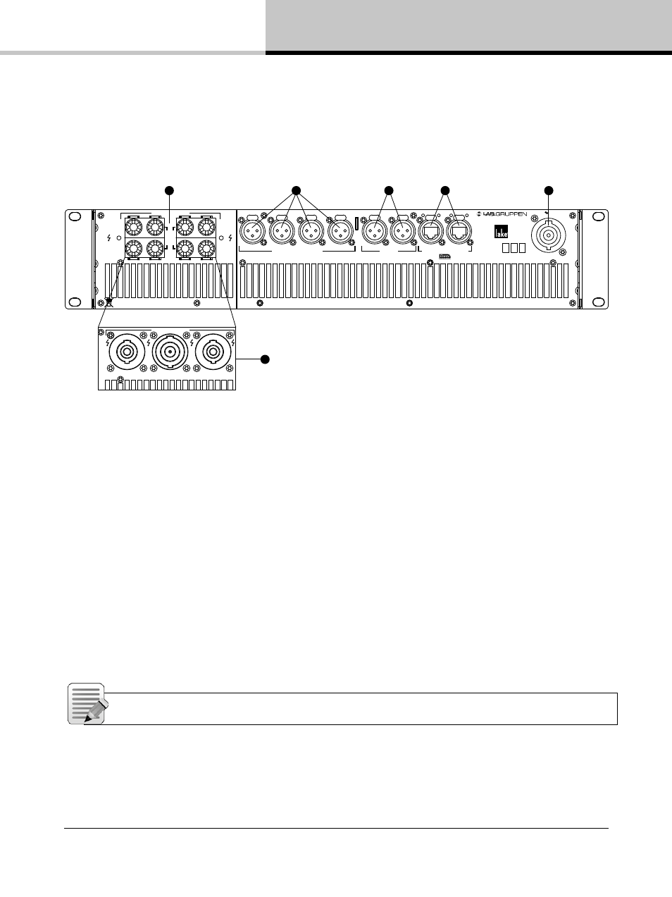
8. Back Panel Interface
PLM+ SERIES Operation Manual rev 1.0.0
57
8. Back Panel Interface
An overview of the back panel interface is provided in section 4.2. This chapter describes each cluster of
connections as shown in Figure 8.1.
3
4
5
1
2
INPUT 1
INPUT 2
INPUT 3
AES/EBU
INPUT 1-2
INPUT 3-4
SEC
PRIM
Must be grounded/earthed
Made in Sweden
PIN 1: SCRN 2: POS 3: NEG
ANALOG WITH
I
SO-
F
LOAT
TM
50-60Hz
100-240V 2400-2950W
Ser. N:o
Removed!
CH
2
CH
1
CH
4
CH
3
SPEAKER OUTPUTS
CLASS 3 WIRING
BRIDGE
BRIDGE
INPUT 4
SWITCHED 00/ 000 Base-TX
1 1
1Gbps
1Gbps
LINK
ACT
LINK
ACT
PLM 2K44
1
1+/- CH 1+/-
2+/- CH 2+/-
1+/- CH 1+/-
2+/- CH 2+/-
3+/- CH 3+/-
4+/- CH 4+/-
1+/- CH 3+/-
2+/- CH 4+/-
CLASS 3
WIRING
BRIDGE CH 1 & 2:
1+:+
2- : -
BRIDGE CH 3 & 4: 1+ : +, 2- : -
SPEAKER OUTPUTS
INPUT 1
INPUT 2
INPUT 3
AES/EBU
INPUT 1-2
INPUT 3-4
SEC
PRIM
Must be grounded/earthed
Made in Sweden
PIN 1: SCRN 2: POS 3: NEG
ANALOG WITH
I
SO-
F
LOAT
TM
50-60Hz
100-240V 2400-2950W
INPUT 4
SWITCHED 00/ 000 Base-TX
1 1
1Gbps
1Gbps
LINK
ACT
LINK
ACT
PLM 2K44
1
6
Figure 8.1: Back Panel Interface
8.1. Speaker Outputs
The PLM+ is available with either 4 mm binding posts or Neutrik speakON connectors for the outputs.
The outputs of the PLM+ can produce a high voltage. Do not connect or disconnect loudspeaker/s while the
PLM+ is powered on. Never operate the PLM+ with any portion of bare loudspeaker wire exposed.
For speakON connector versions, do not use mating plugs without the rear covers in place.
8.1.1. Bridge Mode
Power outputs may be bridged on all PLM+ models by following the configuration instructions in the Lake
Controller Operation Manual (I/O CONFIG > OUTPUT CONFIGURATION) and the wiring instructions in this chapter.
Bridge Mode can only be activated/deactivated using the Lake Controller software.
Note: When Bridge Mode is activated, CLASS 3 wiring is required.