Operation and performance, Current peak limiter (cpl), Max. sinewave burst power (watts) – Lab.gruppen PLM 20K44 User Manual
Page 19: Plm+ series operation manual rev 1.0.0
5. Operation and performance
PLM+ SERIES Operation Manual rev 1.0.0
19
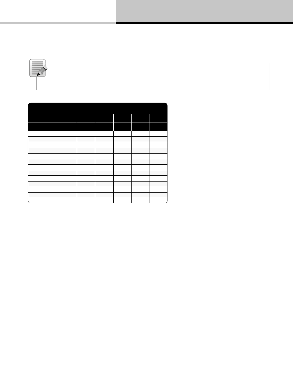
Table 5.3 shows the theoretical maximum output power for a given load impedance and ISVPL setting.
Note: An ISVPL-to-load calculator that will assist in generating the appropriate ISVPL setting for a desired
power load is available at www.labgruppen.com/plm. The ratings shown in the table below are limited by the
CPL (Current Peak Limiter) functions, not by ISVPL settings, due to power output channel current capacity.
Max. Sinewave Burst Power (Watts)
L
Load Impedance (ohms)
2
2.67
4
8
16
L
ISVPL SETTING (V peak)
194
4489
5993
4705
2352
1176
193
4489
5993
4656
2328
1164
181
4489
5993
4095
2048
1024
167
4489
5223
3486
1743
872
153
4489
4384
2926
1463
732
121
3660
2742
1830
915
458
101
2550
1910
1275
638
319
83
1722
1290
861
431
215
70
1225
918
613
306
153
56
784
587
392
196
98
47
552
414
276
138
69
38
361
270
181
90
45
17.8
79
59
40
20
10
Table 5.3: ISVPL-to-output examples
The ISVPL threshold may be set at any level between 17.8 V and 600 V via the PLM+’s menu system. For further
details, please refer to section 7.11.2.5 of this manual, and also to the PLM+ Series chapter in the Lake Controller
User Manual.
PLM+ devices that have a smaller peak output voltage can still set the ISVPL threshold up to 600 V. When a
threshold is set above the maximum capability of a power output channel, the maximum ISVPL for that product will
be automatically set. Therefore, the ISVPL threshold can be in at the Module for the speaker’s maximum capability,
and the Module file remains cross-compatible with all PLM and PLM+ Series devices.
5.3.2. Current Peak Limiter (CPL)
The output Current Peak Limiter (CPL) ensures that the power output section will not be damaged by forcing it to
deliver current levels at the outputs that exceed the maximum current ratings of the output transistors. The CPL
keeps the output transistors within their Safe Operating Area (SOA). The CPL is non-adjustable.
CPL activity is indicated on the power output channel LED (embedded in the associated output channel’s function
button to the right of the LCD). Activity on an affected channel results in a flashing red indication together with a
CURRENT CLIP warning message displayed on the screen adjacent to the LED. A warning is also displayed on
the controlling PC via the network.